This post belongs to the series of posts about the Meshtastic BuildOff 2026. The previous posts are:
https://myembeddedstuff.com/meshtastic-build-off-2026-retromeshdevice
https://myembeddedstuff.com/meshtastic-build-off-2026-pcb-assembly
https://myembeddedstuff.com/meshtastic-build-off-2026-hardware-bring-up
The final remaining step for my device was to compile the Meshtastic firmware for my board.
Official repo: https://github.com/myembeddedstuff/RetroMeshDevice
Table of Contents
ToggleMeshtastic implementation
Before starting with the integration of my device into the Meshtastic firmware, it is worth taking a moment to understand how it is structured. In case there were any doubts, it is important to highlight that this is an open-source project fully written with all the Mesh communication protocol logic already implemented, along with many functional modules. Therefore, our main job is simply to define our hardware guidelines and pinout connections.
Additionally, if a specific module is not available, it must be implemented following Meshtastic’s framework to maintain a consistent structure across the project.
PlatformIO
First of all, it is important to know that this project is built on top of the PlatformIO framework, where everything relies on a platformio.ini file located at the root of the project to define each build target.
The great thing about PlatformIO is that it can be integrated directly into VSCode by installing its official extension. It is very straightforward and allows you to stay within the familiar VSCode environment you are already comfortable with.
Once you have cloned the Meshtastic repository and have it working, PlatformIO handles downloading all required dependencies, compiling the code for a specific hardware platform, and generating the binary files to flash onto your board (.bin or .uf2). To do this, you simply execute a command like:
pio run -e 'target_name'I won’t go into detail about setting up the build environment, as the official documentation already covers this step-by-step and stays up to date:
https://meshtastic.org/docs/development/firmware/build/
Now, let’s dive into a few key concepts essential for firmware development, such as Variants and Modules.”
Variants
A Variant is the set of files that defines our hardware. Essentially, it tells Meshtastic which pins you are using, which peripherals are connected, and what your board is named.
This is what PlatformIO uses to determine which modules to compile, under what conditions, and which configurations to apply. Core features—like the underlying Mesh communication protocol—will always be included, but specific choices like the RF module, whether an OLED display is present, or which ADC pin is used for battery monitoring must be explicitly defined somewhere.
Variant files are located in variants/your_board_name/ and typically contain at least these two files:
Variant.h
variant.h. It is the main file. Here, you define all the pins and hardware capabilities of your board using #define directives. For example:
Whether you include battery monitoring and which pins are assigned to it.
Whether you have an OLED display and which specific model you are using.
Which radio module is integrated.
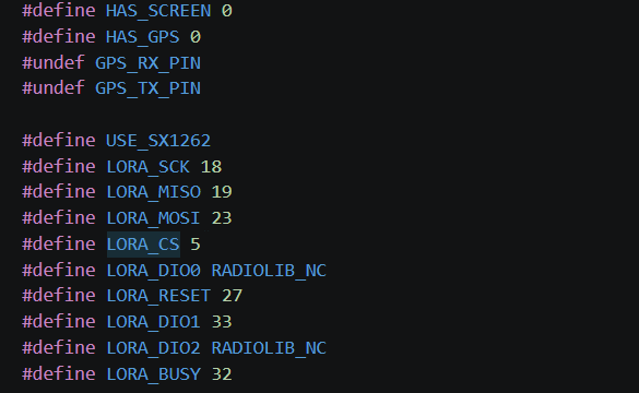
For example, the following image shows a variant that does not feature a display or GPS, and uses the SX1262 LoRA module.
Platform.ini
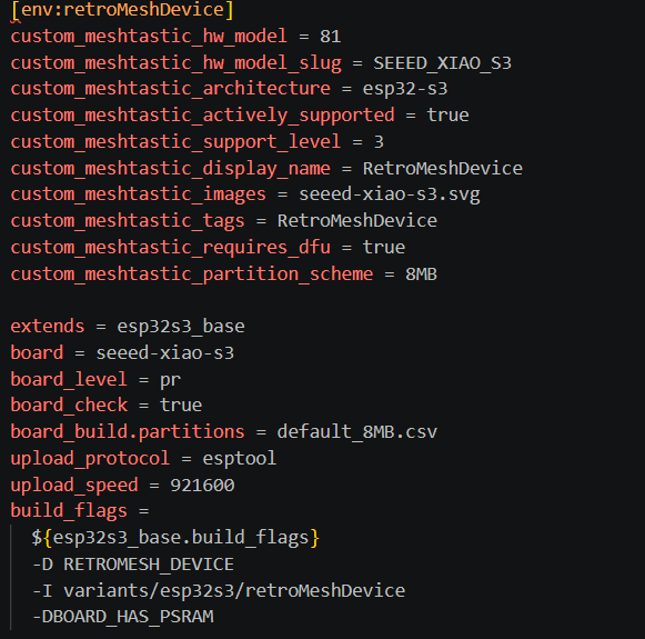
platformio.ini Here you add a new build environment that points to your variant. You specify parameters such as whether it is based on an ESP32, if it shares configuration with similar boards, the upload speed, and compilation flags, among other options.
Pins_arduino.h
pins_arduino.h Here you specify the default pin mapping for I2C (SDA, SCL), the SPI bus (MISO, SCK, MOSI, SS), and USB identifier info (PID, VID).
Modules
Beyond basic pin definitions, Meshtastic features a modular architecture. Modules are optional capabilities that can be enabled or disabled depending on your needs: telemetry, position tracking, alerts, external keypads, and more.
If your hardware includes custom features—like in my case, the T9 keypad driven by an MCP23017—you will also need a driver that implements the interface expected by Meshtastic. For my build, I had to write a custom class inheriting from the project’s base keypad class, implementing key-reading logic via the I2C port expander.
Implementing the RetroMeshDevice
With these concepts clear, I will explain how I completed the firmware integration for my RetroMeshDevice.
I would like to highlight how impressively structured the Meshtastic project is. They have integrated robust CI pipelines for pull requests, automated bots to catch bugs before reviews, comprehensive unit tests, and more. If you want to learn how a large-scale open-source embedded project operates, diving into their workflow is a fantastic resource for your own personal projects.
To start implementing my target, the first step was creating a local clone of the latest Meshtastic repository.
Once cloned, my recommendation is to first build the project for an existing, similar board. In my case, I picked the seeed_xiao_s3, as my hardware builds around that module (I covered this setup previously in this post: https://myembeddedstuff.com/meshcore-vs-meshtastic-seeed-studio).
To run the initial test compilation, execute:
pio run -e 'seeed-xiao-s3'Once the build finishes successfully, you can upload it directly via PlatformIO. Alternatively, since the .bin output file is generated, you can flash it using your tool of choice:
pio run -e 'seeed-xiao-s3' -t uploadRetromeshdevice variant implementation
Once you have confirmed that you can build and flash Meshtastic onto a test target, it is time to start on your custom implementation.
As a helpful tip, you can copy an existing variant folder and rename it to match your board, then adjust the settings as needed.
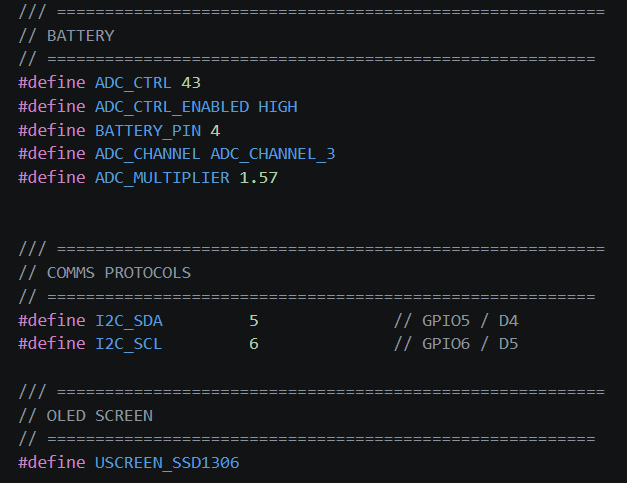
For example, in my setup I configured battery monitoring using an enable line on GPIO43 and the analog measurement on Pin 4. Based on the resistor divider chosen in my schematic, I set a scaling factor of 1.57. I also specified the OLED controller model used in my build.
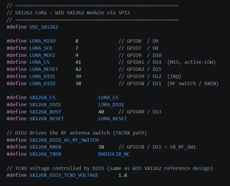
Next, I specified the LoRA module used and defined the exact pin mappings connected on my board.
Finally, I needed to define the buzzer assigned to Pin 3. However, this line remains commented out because I discovered a hardware design bug where the buzzer was actively driven logic-low.
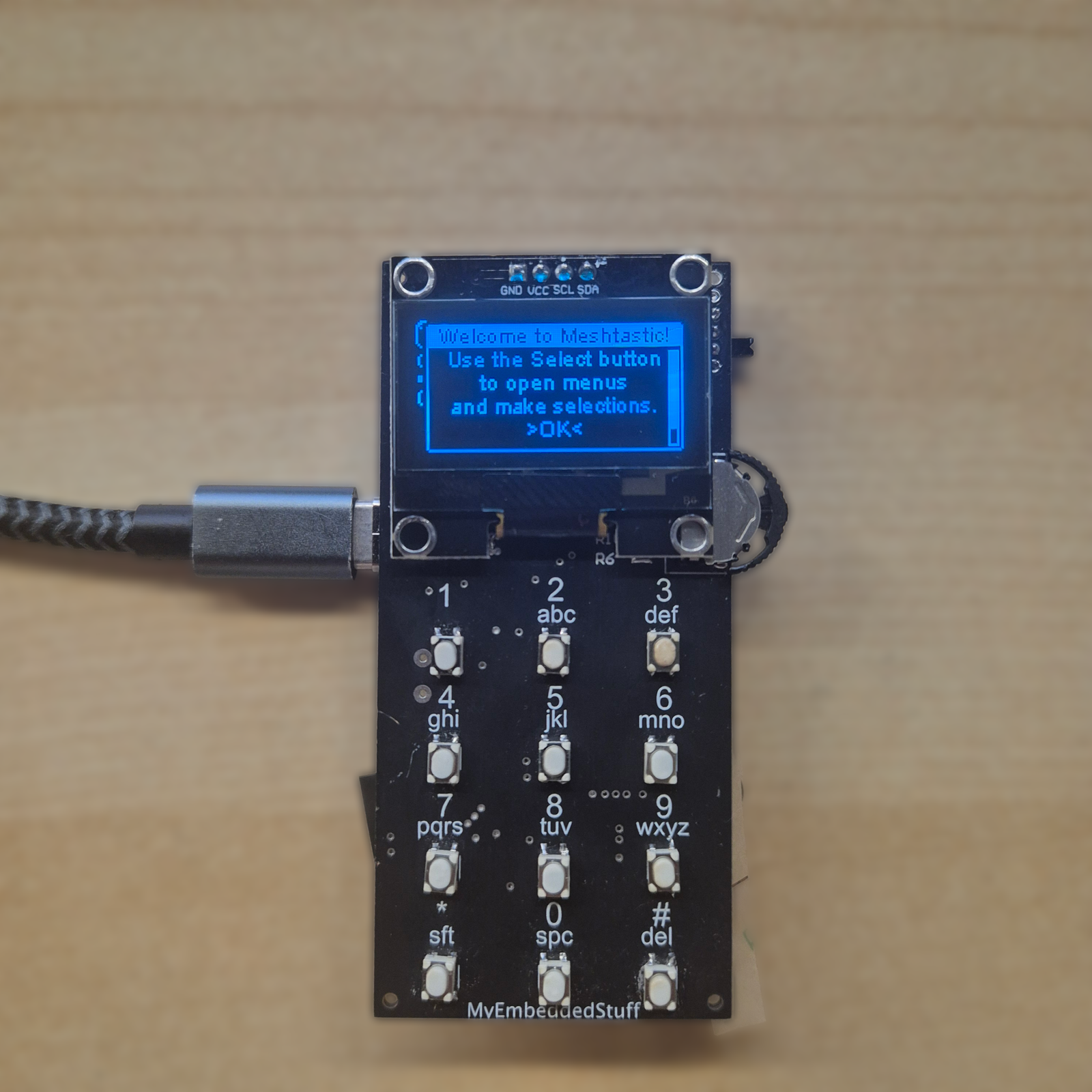
This is why the buzzer is omitted in the photos I shared—those images show the second assembled revision of the PCB, which I built after catching that mistake on the first board.
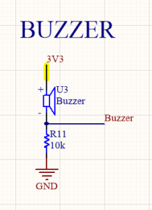
While this could be fixed in software by inverting the control logic, looking closely at my hardware layout, it didn’t make much sense to implement a workaround that wouldn’t benefit the wider community. It makes far more sense to note it down as a revision item and fix the trace routing on the next PCB iteration.
MCP23017 driver implementation
For the T9 keyboard on the RetroMeshDevice, I needed a dedicated driver. I used Meshtastic’s existing MPR121Keyboard implementation as a foundation and adapted it to match the register map of the MCP23017.
The class supports two I2C communication modes: direct Wire access or custom read/write callbacks, allowing you to select the appropriate method in begin() depending on how the port expander is integrated into your hardware.
Inside reset(), I configure all 16 pins as inputs with internal pull-ups enabled, setting interrupts to trigger on logical change (comparing against the previous state rather than using DEFVAL). Additionally, IOCON is configured with active mirroring disabled, as my hardware design routes INTA and INTB independently to GPIO1 and GPIO2.
Keypress management relies on the state machine original to MPR121 (Idle, Held, HeldLong, Busy), which is regularly polled and evaluated inside trigger(). During polling, GPIOA/GPIOB are read together as a single 16-bit register to evaluate pin states. Active bits map to logical key indices (0–14) through MCP23017_KeyMap[]. This lookup table bridges the gap between the physical connector pinout and the logical layout of the keypad.
Once mapped to an index, each key supports dual-mode behavior based on hold duration:
Short press (tap): Releasing a key within the multi-tap window (
MULTI_TAP_THRESHOLD, set to 2 seconds) incrementschar_idxto cycle through character options inMCP23017_TapMap[][](the classic T9 mapping where key2cycles through'a','b','c'). The total character count for each key is defined inMCP23017_TapMod[]to handle modulo wraparound correctly.Long press: Holding a key past
LONG_PRESS_THRESHOLD(1 second) bypasses the release listener. Instead,held()directly emits the corresponding character fromMCP23017_LongPressMap[]—a single-character lookup table storing primary numbers or directional navigation controls like Up, Down, and Escape.
You can inspect the full implementation details in the PR: https://github.com/meshtastic/firmware/pull/11015
Note: While the complete integration involves additional files—such as the driver header,
variant.hbindings, and I2C scanner registration—focusing on the main source file captures the core logic behind the custom driver.
How to Integrate the MCP23017 Driver
Once you have the driver up and running, the next step is adapting the keymap array to match your specific hardware layout. The default sequential mapping (MCP23017_KEYMAP_0 through 15 corresponding to bits 0 to 15) almost never aligns with how the keypad traces are physically routed to Ports A and B on the expander.
To make this seamless, the driver checks for a custom configuration flag:
By defining CUSTOM_MCP23017_MAP in your board configuration before including the driver header, you can override the default mapping with your hardware pinout without modifying the driver source code.
Looking at the schematic, GPA0–GPA7 and GPB0–GPB7 do not follow a sequential relationship with the keypad labels (K_1, K_2, K_4…) on the PCB:
Example: On my board,
GPA0routes to physical keyK_8, which corresponds to logical index 7 (sinceK1represents index 0 in the software logic)
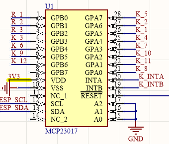
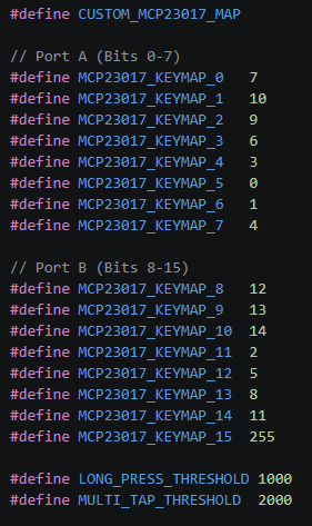
Setting 255 for MCP23017_KEYMAP_15 is intentional: my layout only uses 15 keys (indices 0–14), so leaving that unused 16th bit mapped to an out-of-bounds value ensures it will never accidentally evaluate to a valid keypress.
In this same configuration block, you can also override LONG_PRESS_THRESHOLD and MULTI_TAP_THRESHOLD to tune the key response timing to your preference, without having to touch the driver source code.
Conclusions
And with that, my RetroMeshDevice was fully operational on official Meshtastic firmware—complete with active battery monitoring, an OLED display, configured LoRa radio parameters, and the T9 keypad operating via the MCP23017. What started in the earlier posts of this series as just a freshly soldered PCB has now become a fully functional, usable Mesh node.
If this integration taught me anything, it is that most of the effort is not about writing brand-new code from scratch, but rather gaining a solid understanding of how the framework is organized. Once you grasp what variant.h handles and where PlatformIO links each build macro, adding custom hardware—especially when built around established modules—becomes a straightforward process.
Note: If you enjoyed this build and want to support the project, please consider leaving a like on my official GitHub Issue #10. I am currently participating in the Seeed Studio BuildOff, and your support means a lot!