
This post belongs to the series of posts about the Meshtastic Build Off 2026. The previous posts are:
Note: If you like this content and project, please consider giving a like to the following GitHub issue where I discuss my latest progress. I am currently participating in the BuildOff, and your support would mean a lot! https://github.com/Seeed-Projects/meshtastic-build-off-2026/issues/10
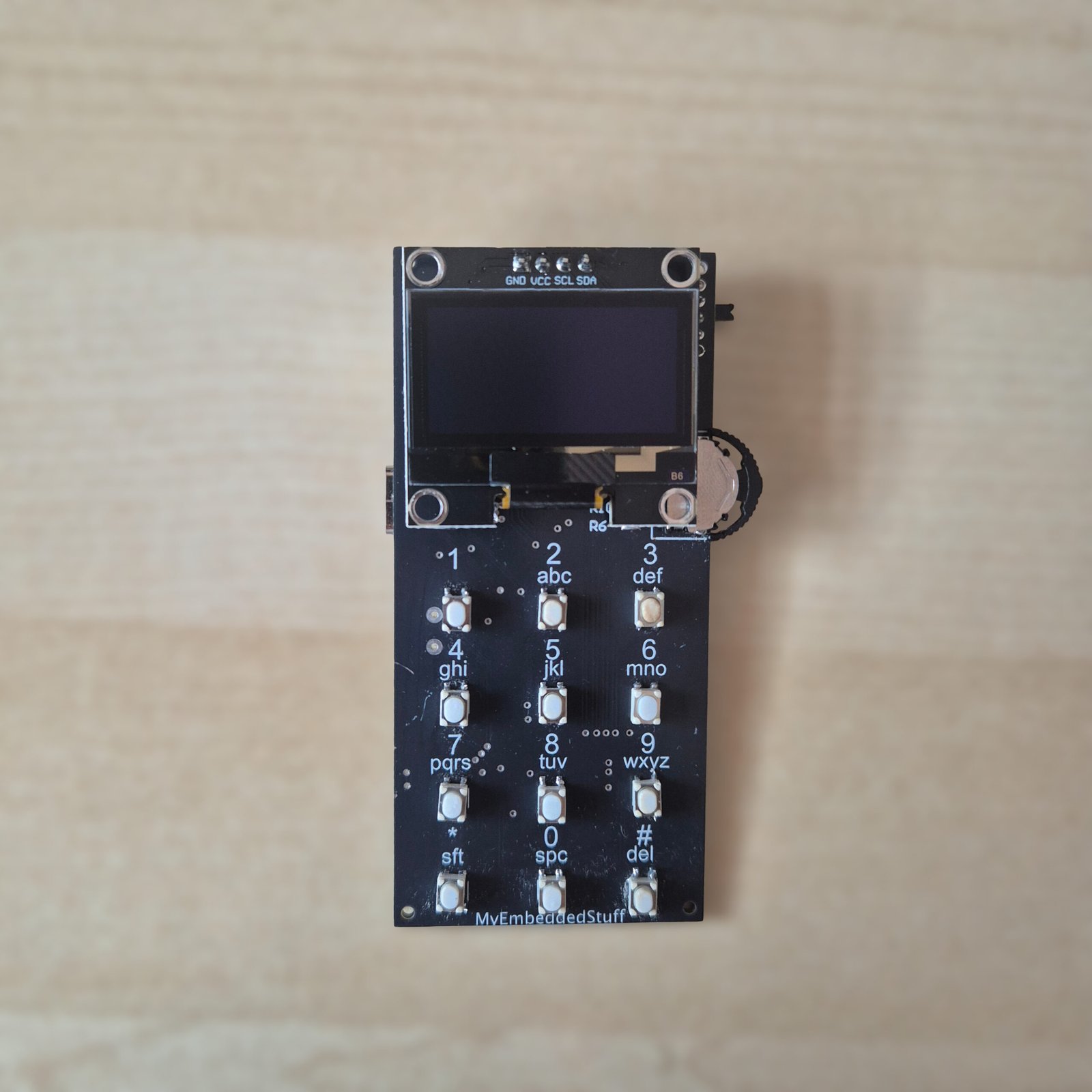
As a continuation of the project, I have already received the first version of my design. Since I did not order the boards preassembled, the next step was to assemble them myself. In this post, I want to explain what the board assembly process was like and the final result. Additionally, I will discuss some aspects that I have identified for improvement in future versions.
First, I will explain the necessary steps for assembly when ordering the PCB, what tools I used and which ones I recommend, and finally, some photos showing how the assembly turned out.
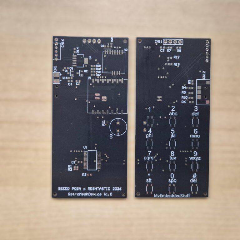
Table of Contents
ToggleAssembling the first version of the PCB
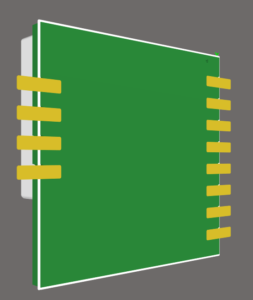
The component that increased the assembly complexity of this board the most was the XIAO ESP32S3Plus module. This is because this module features several pads on its underside, which makes it significantly more complex to solder by hand.
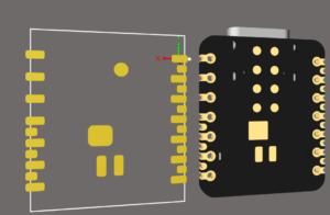
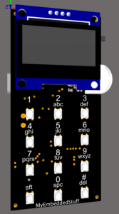
Note that not all pads were necessary for me, which is why many of them are not included in its footprint. On the right you can see the 3D model and on the left the footprint designed in Altium.
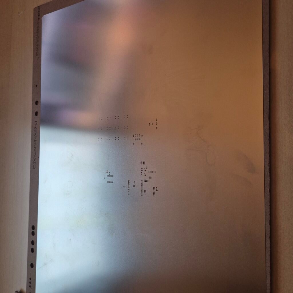
Due to this complexity, when placing the order for the PCBs, I acquired its stencil for the assembly.
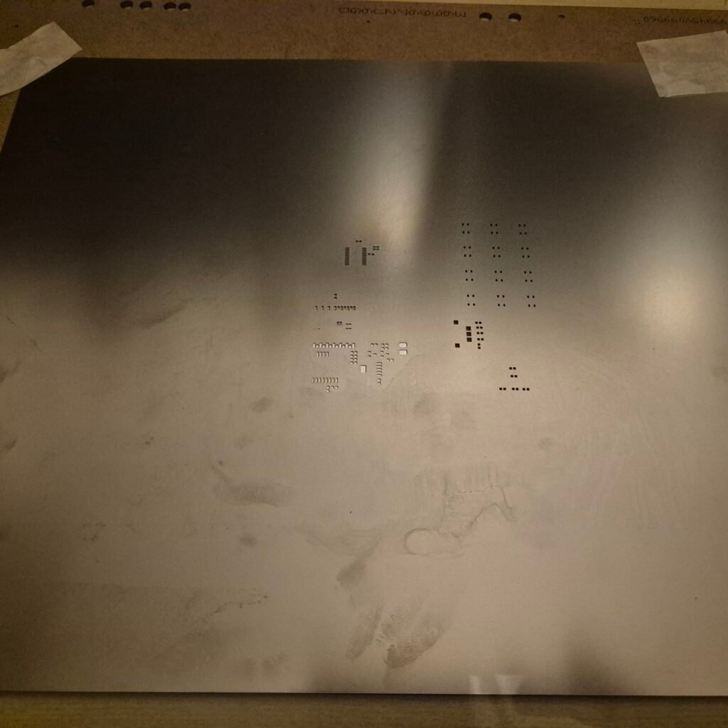
The stencil
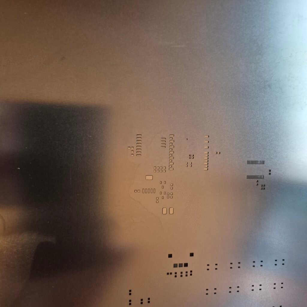
The stencil is a metal plate that contains the holes for the pads of your PCB design. You can choose a stencil for either a single side or both. The idea is that when you position the board with the stencil, you can apply the solder paste so that it is perfectly distributed across all the pads.
This way, by simply placing the components and applying heat through different methods, such as an oven or a heat gun, everything is properly soldered with the right amount of solder paste.
As a result, assembling your board will be much faster than using the traditional method of a soldering iron.
The remaining components are quite easy to solder since they do not have pads on the underside. For example, the WIO SX1262 LoRa module features simpler pads that you can solder without any issues using a standard soldering iron. If your design only includes components of this type, you can save money by skipping the stencil, although the time you spend assembling your board will be longer.
Tools I used
For this build I picked up a few things that might be useful if you’re planning something similar.
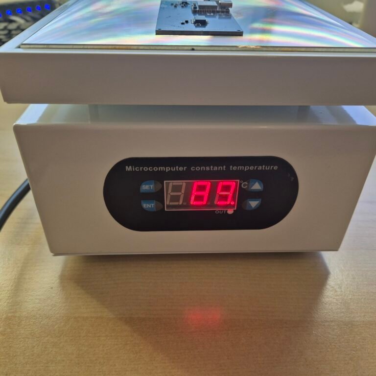
Preheating station
First up is this preheating station. The idea behind this equipment is to heat the base of the PCB to a moderate temperature, which then makes the assembly easier when you apply a bit of extra heat with another tool. You could even solder a single-sided board using just this station if you raise the temperature above 250ºC.
On the equipment I chose, the dimensions of the base are slightly larger than others. You can reduce the cost by purchasing one with a smaller base, but due to the dimensions of my PCB and in case I make larger designs in the future, I decided on this one. It is very simple to configure since you just connect it to the power supply and set your target temperature. It does take a little while to reach the temperature, but it more than does the job.
Hot air soldering station
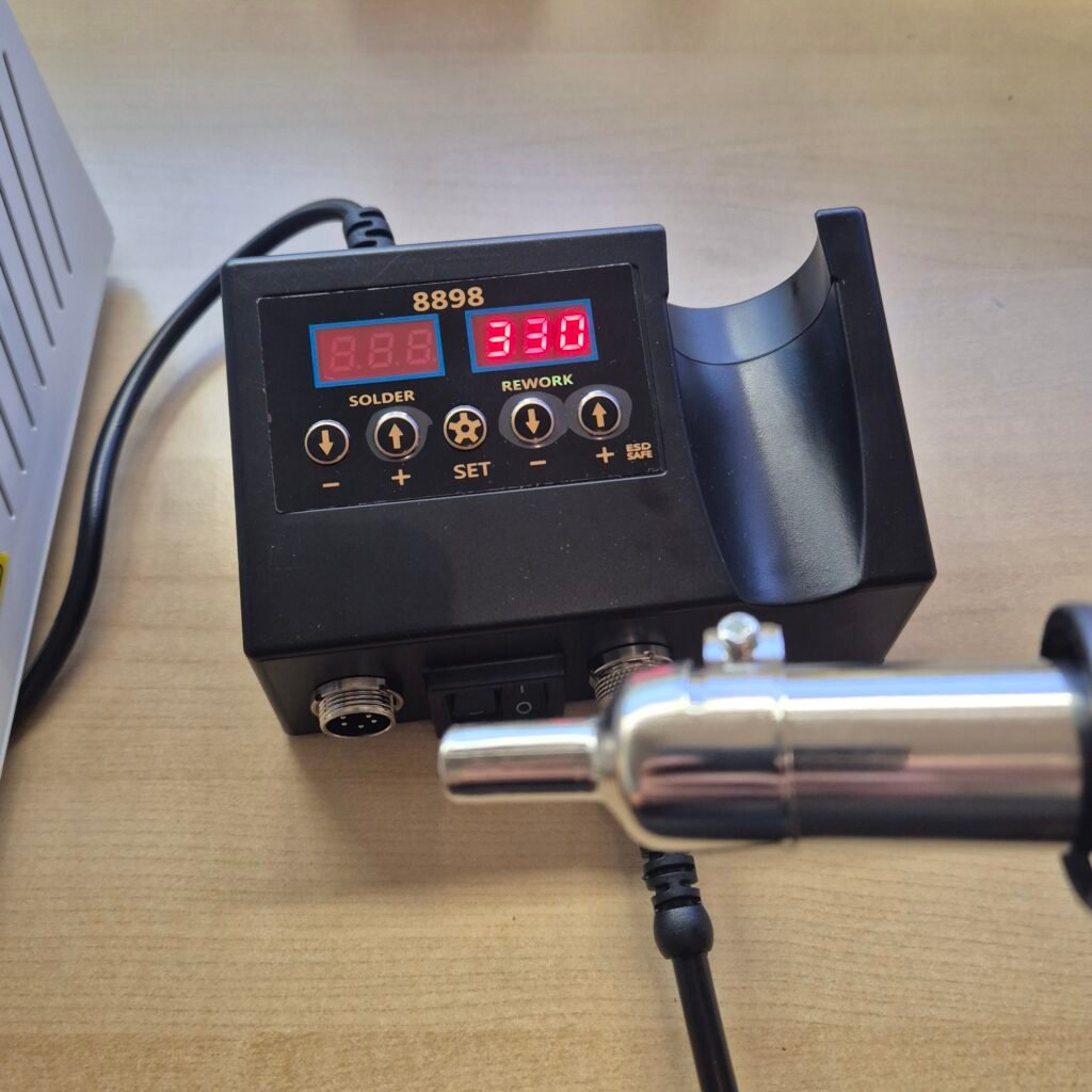
The other product I needed was the hot air gun for soldering. The purpose of this equipment is to apply that necessary extra heat in a focused manner on the components so they can be soldered.
In my case, I acquired this station which includes the soldering iron to be able to switch quickly if I need to use it at some point. You will not be able to solder everything this way, for instance, for through-hole components it might be better to solder them at the end with a soldering iron.
This is not the most advanced station, but it gets the job done. For standard soldering I usually use the TS101 soldering iron (Aliexpress click to buy) which is highly recommended, but since I needed a hot air gun, it seemed like a better idea to get a 2-in-1 kit and avoid cluttering the workbench with tools.
Assembly process
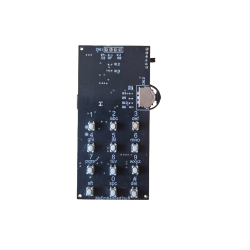
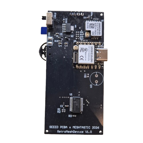
I am attaching some photos of the assembly so you can see how it turned out.
Applying solder paste
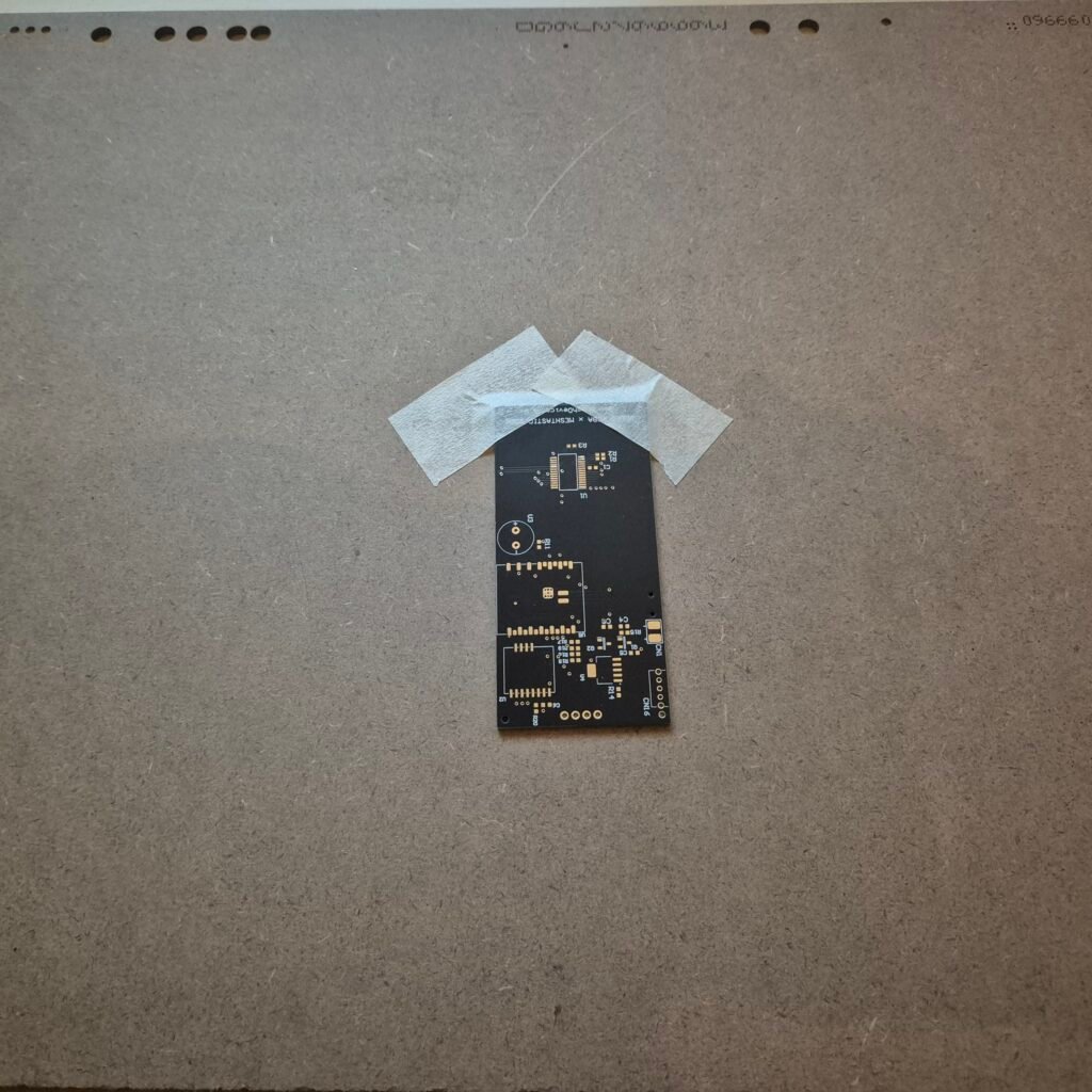
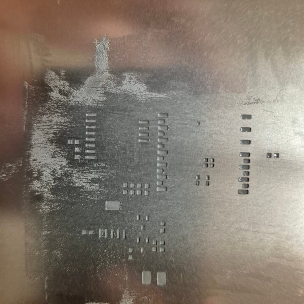
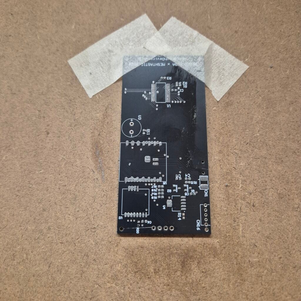
First, you need to apply solder paste to the side you want to assemble. To do this, you must place the stencil you acquired over the board. I recommend using masking tape to keep the board fixed in place, as any tiny movement will cause the solder paste to be applied incorrectly across the pads, especially when dealing with small pads.
Once positioned, simply apply the solder paste and spread it evenly across the entire board. You can use a plastic spatula or an old card to apply it so that all pads are covered. Remove it carefully so that you do not lift part of the solder paste when pulling the stencil away.
Placing the components
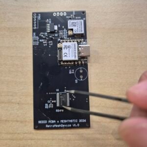
Next is the process of placing all the components onto the board. This simply involves following the BOM (Bill Of Materials) and checking which component needs to go in each spot. It is just a matter of patience.
Reflowing
Once they are placed, we can position our board on the preheating station and bring it to a temperature between 100 and 150ºC, which will keep the base warm but not hot enough to melt the solder.
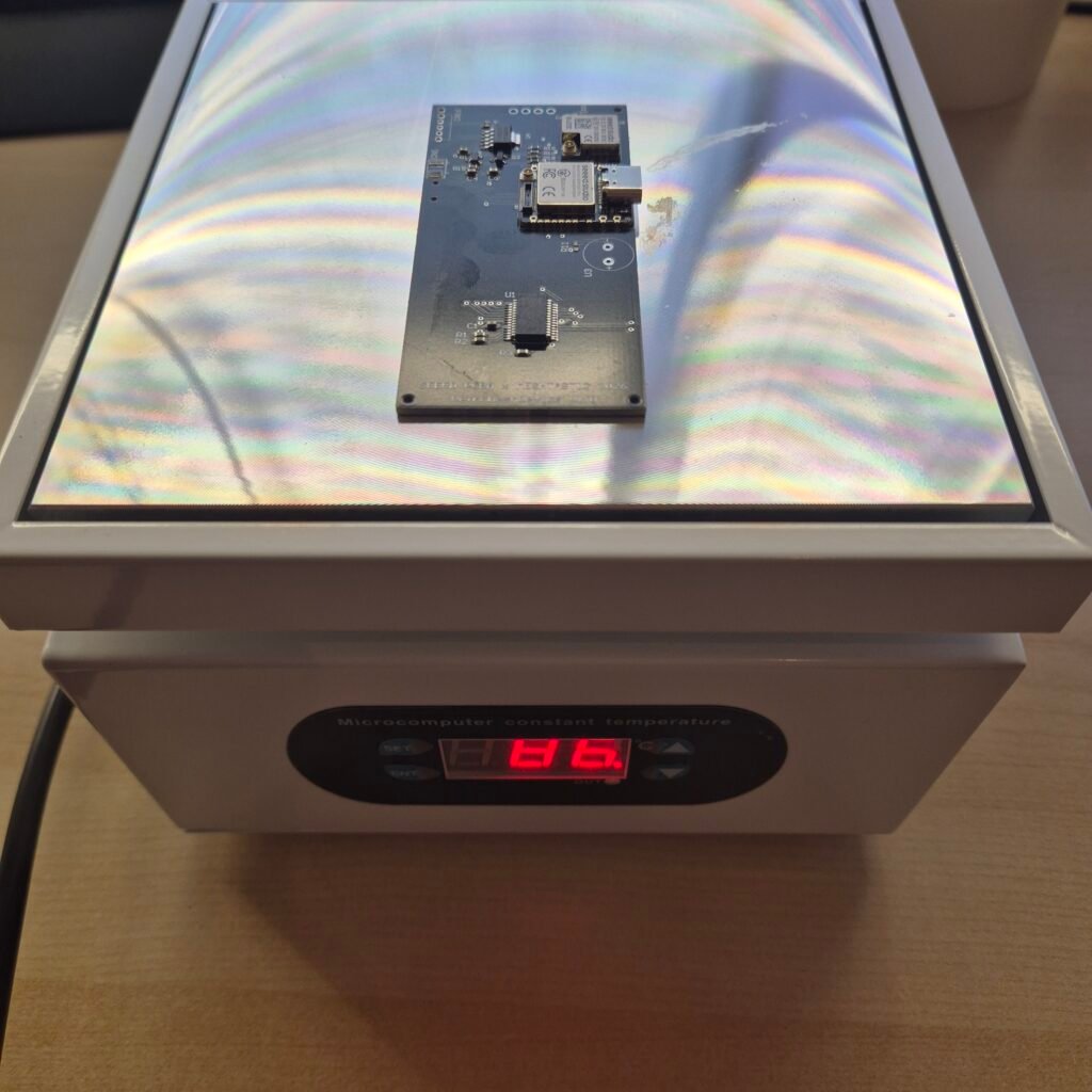
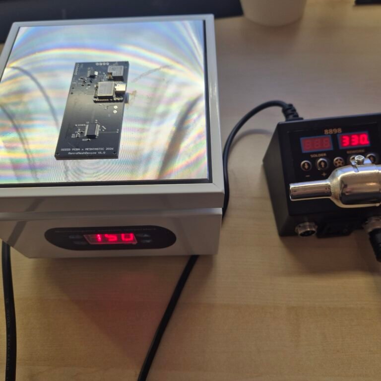
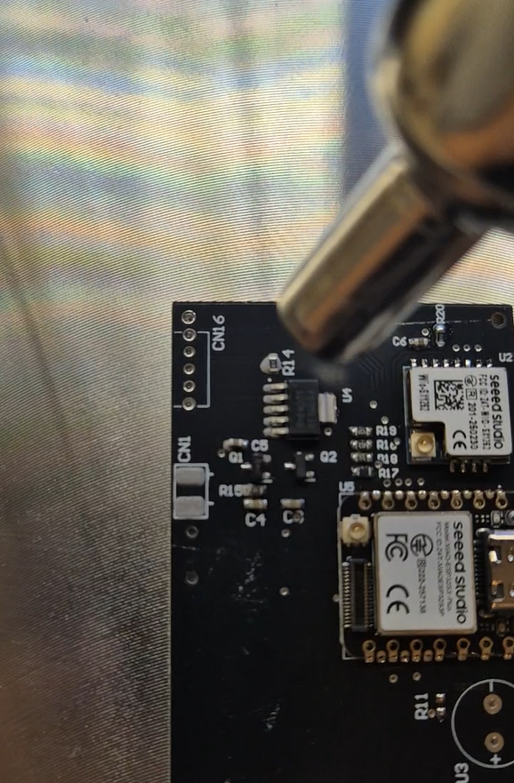
When it reaches that temperature, with the help of the hot air gun, we can apply heat to each component so it solders. You must pay special attention to the ones with pads on the underside to ensure it reaches a high enough temperature for the solder paste to activate.
Finally, you will need to assemble some components by hand. For example, in my case, the OLED display has to be soldered separately and manually. It is straightforward since it uses standard 2.54 mm pins.
Things I'd fix in the next revision
Regarding improvements, there are a couple of things that I have already identified for the next revision.
The silkscreen for the battery connector is not well positioned. The border of the component silkscreen completely covers it, making it barely distinguishable which is positive and which is negative.
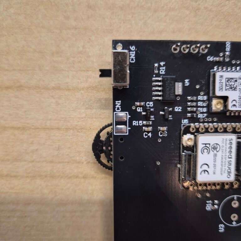
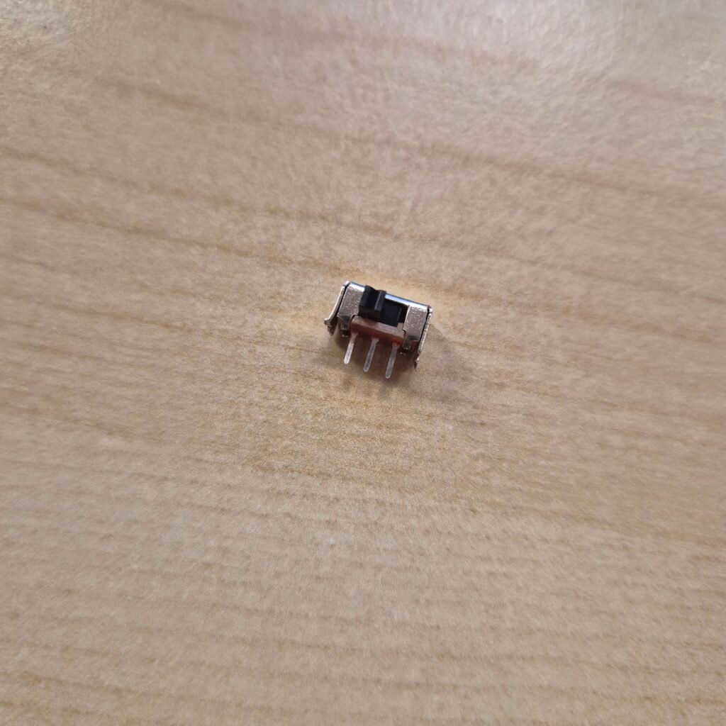
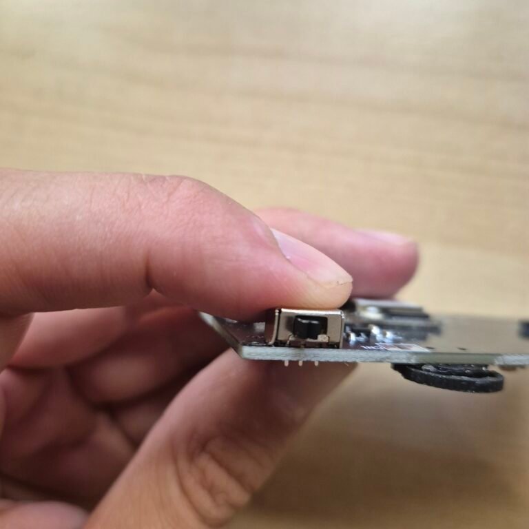
The other issue was with the slide switch. I designed the pad incorrectly and did not leave enough clearance for the anchoring pins, so they did not fit properly into the board. For the prototype, I resolved this by cutting those pins off directly, since their only function is to secure the switch mechanically and they have no electrical purpose. Even so, with a bit of solder, it was successfully secured anyway. It is not the most elegant solution, but it works perfectly to validate the prototype.
Final thoughts
If you have made it this far, you already have a pretty clear idea of what it takes to assemble a board of this type at home. It is not as complicated as it seems, but it does require a bit of equipment and, above all, patience with the stencil and the solder paste.
One thing I have seen people do that makes me curious is using low-temperature solder paste along with the preheating plate, without needing a hot air gun. In theory, it simplifies the process quite a bit. Has anyone tried it? I am interested in knowing how well it works in practice before considering it for the next revision.
In the next post, I will explain the board testing process.
I find a good amount of flux under the castellated holes helps wick up under then nicely. Thanks for sharing your progress thus far.
Yes, flux works very well, but I’ve never used it with a soldering gun. It helps a lot when I solder with a soldering iron. Thanks for sharing!
Great write-up! The slide switch anchor pin issue is a classic first-spin mistake — easy to miss when you’re focused on the electrical footprint and forget the mechanical clearance. The silkscreen polarity label getting buried under the component courtyard is something that bites almost everyone at least once too.
One tip for the low-temperature solder paste question: it works well on a preheating plate, but watch out for components with tight thermal mass differences on the same board — you can end up with one side reflowing before the other side is ready. Worth testing on a sacrificial board first.
If anyone reading this wants to skip the v1/v2 iteration pain on a similar IoT hardware project and go straight to a production-ready design, our team at Daksh Kanya handles exactly this — PCB design, DFM review, and embedded firmware: dakshkanya.com/embedded-hardware-design-services/
Pingback: Meshtastic Build-Off 2026: Hardware Bring-up and Initial Validation - myembeddedstuff.com
Pingback: Meshtastic Build-off 2026 - Meshtastic firmware implementation - myembeddedstuff.com