Not all antennas that come with Meshtastic and MeshCore kits are equal, even if they look the same. While testing these networks, I’ve come across a wide variety of antennas — many of them bundled with different kits I’ve picked up along the way. It’s true that in field tests, some of them allow you to reach further and get better performance with the same hardware, but you never really know exactly why.
That got me wondering whether I could characterize them using some kind of equipment, rather than relying on field tests and trial and error. After some research, I came across a tool born from the maker world that lets us measure LoRa antennas at 868 MHz easily and without the need for expensive lab equipment: The NanoVNA.
Table of Contents
ToggleNanoVNA
As a fun fact, this tool was born in 2016 by a Japanese amateur radio operator as a fully open source, low-cost device designed to analyze vector networks. Although the first prototype was quite basic, it has evolved significantly into its current design, which includes a touchscreen and a much wider frequency range than in its early days.
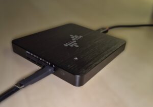
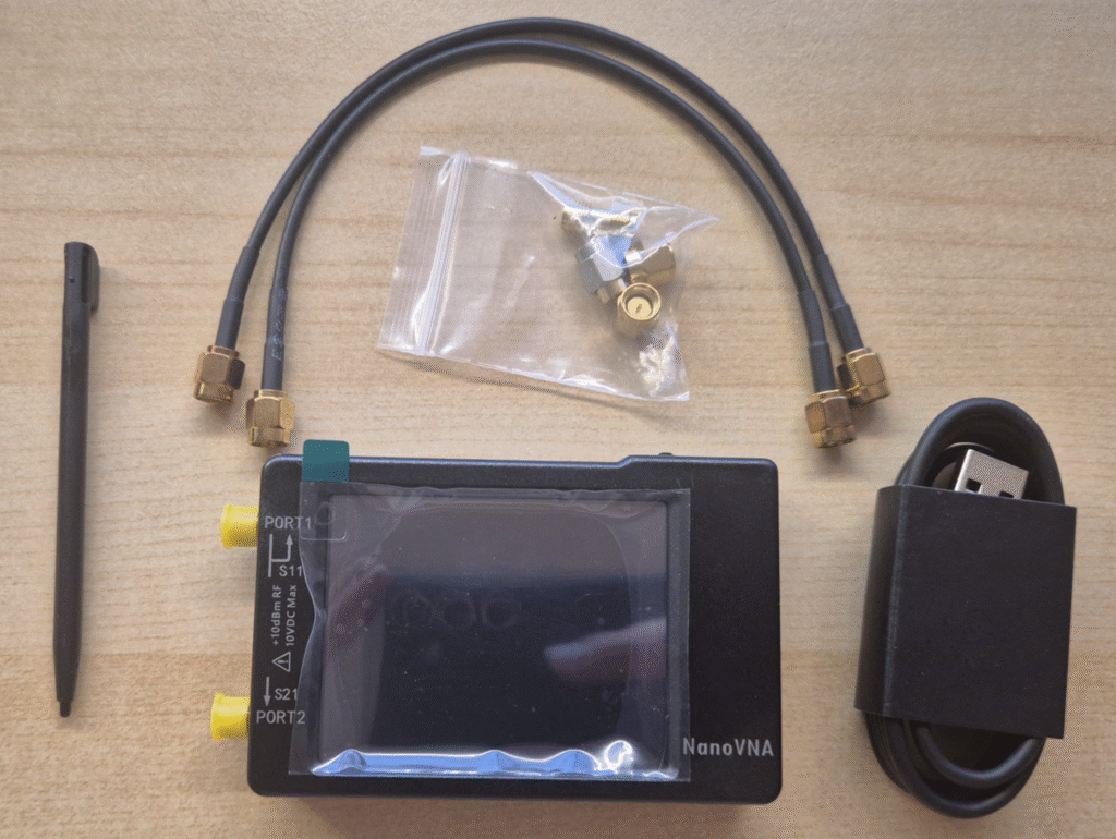
The kit contents are as follows:
- NanoVNA body
- SMA Load 50Ω
- SMA Short
- SMA Open
- SMA Female to Female Through Connector
- SMA Male to Male cable x2
- Stylus
- USB cable
Calibration
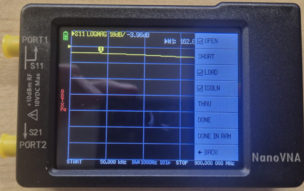
- OPEN → connect the SMA Open connector to port 1 and tap OPEN
- SHORT → connect the SMA Short connector to port 1 and tap SHORT
- LOAD → connect the 50Ω resistive load to port 1 and tap LOAD
- ISOLN → connect the 50Ω resistive load to port 2 and tap ISOLN
- THRU → connect the male to male cable between port 1 and port 2 and tap THRU
Once all steps are done, tap DONE and you’ll see the following menu:
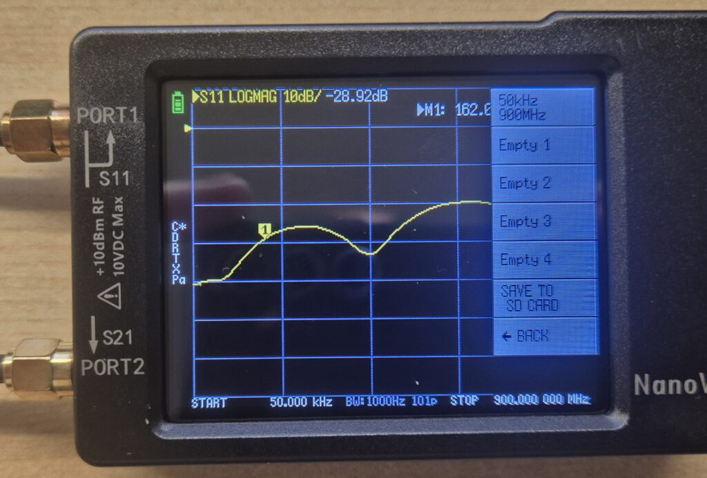
To save the calibration, go to SAVE and select one of the available slots.
Calibration verification
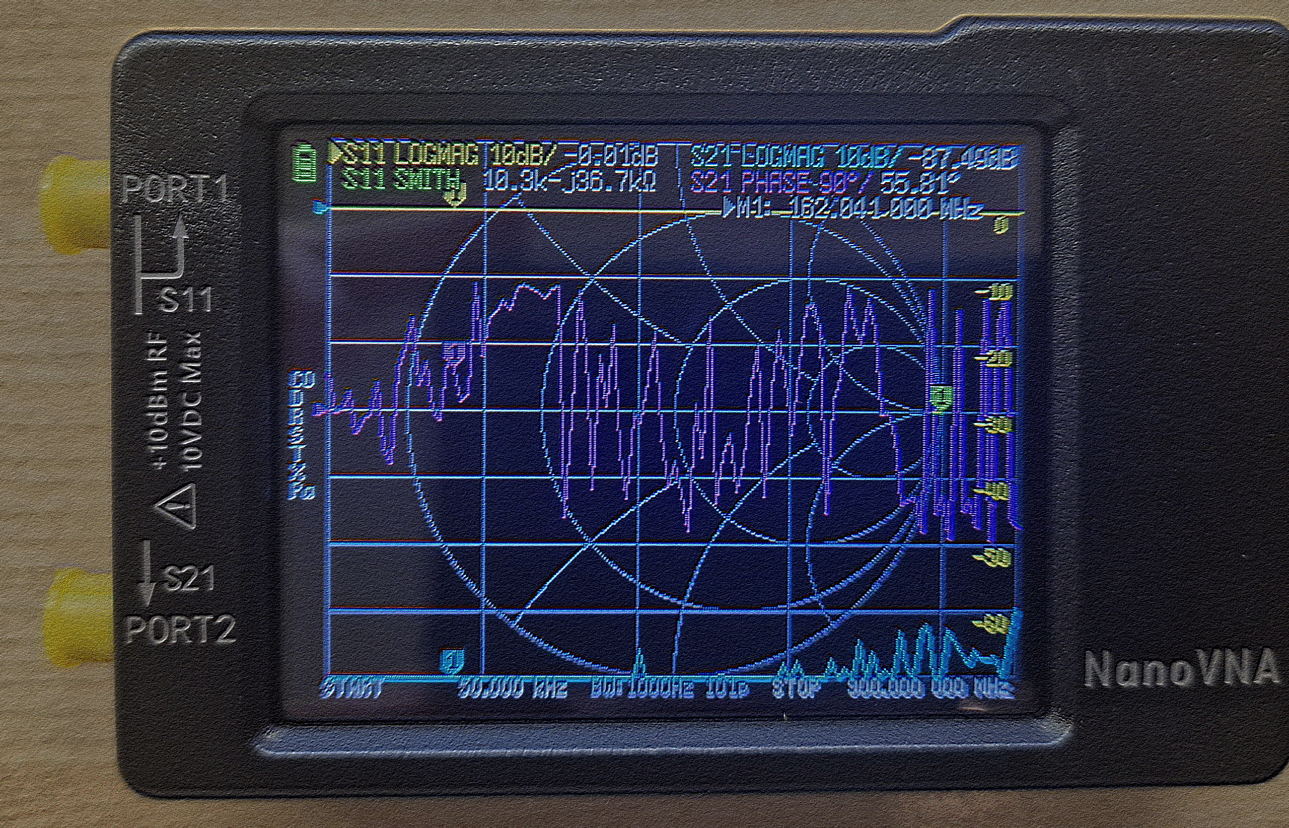
To make sure the calibration process went correctly, we’ll check it using the Smith chart.
Note: The Smith chart is a graphical representation of the impedance of an RF component. Instead of showing numbers, it places a dot inside a circle where the center represents the ideal 50Ω impedance, the left edge represents a short circuit (0Ω), and the right edge represents an open circuit (∞Ω).
Go to DISPLAY → FORMAT → SMITH
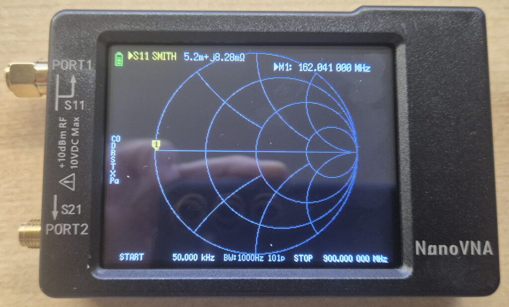
Verify the following:
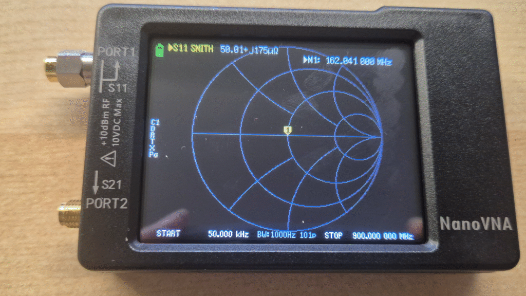
(1) Connect the 50Ω load to port 1. The dot should appear exactly in the center of the chart. This represents purely resistive impedance with no reactive component.
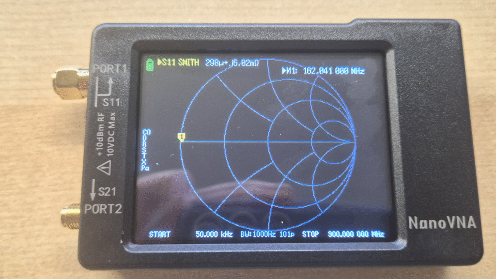
(2) Connect the SHORT load to port 1.
The dot should appear shifted to the left, representing zero impedance.
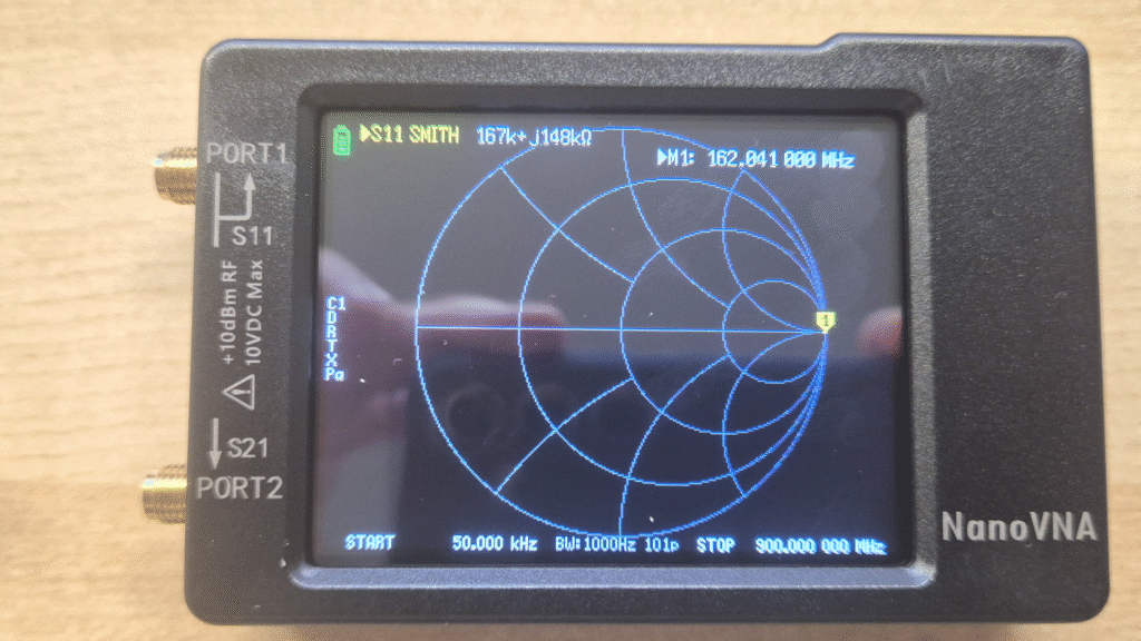
(3) Leave all ports disconnected.
In this case the dot should appear on the right side, representing theoretically infinite impedance.
Once you’ve confirmed the calibration is correct, we can move on to measuring antennas.
Test antennas
Since frequencies (Meshcore and Meshtastic network) are usually centered around 868 MHz, I’ll walk through the whole process for this range. If you’re working at 433 MHz in your region, just pick the corresponding frequencies.
Go to Menu → Stimulus
Select Start and enter 668 MHz (200 MHz below 868 MHz) Select Stop and enter 1068 MHz (200 MHz above 868 MHz)
This way the frequency of interest ends up centered on screen.
Once the range is set, connect the antenna you want to measure to port 1 (the left connector on the NanoVNA). Go to DISPLAY → FORMAT and select SWR on the active trace — it’s the most intuitive metric for evaluating antennas.
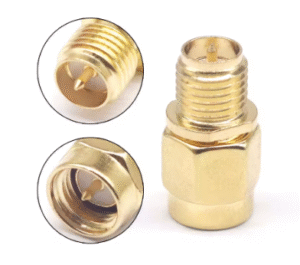
IMPORTANT NOTE. In my case the antennas I have are SMA female type, so if connected directly to the NanoVNA — which is also female — there will be no physical connection and you won’t see anything. Consider buying the following SMA-J a RP-SMA-K adapter to be able to take measurements.
https://s.click.aliexpress.com/e/_c3DfoKBB
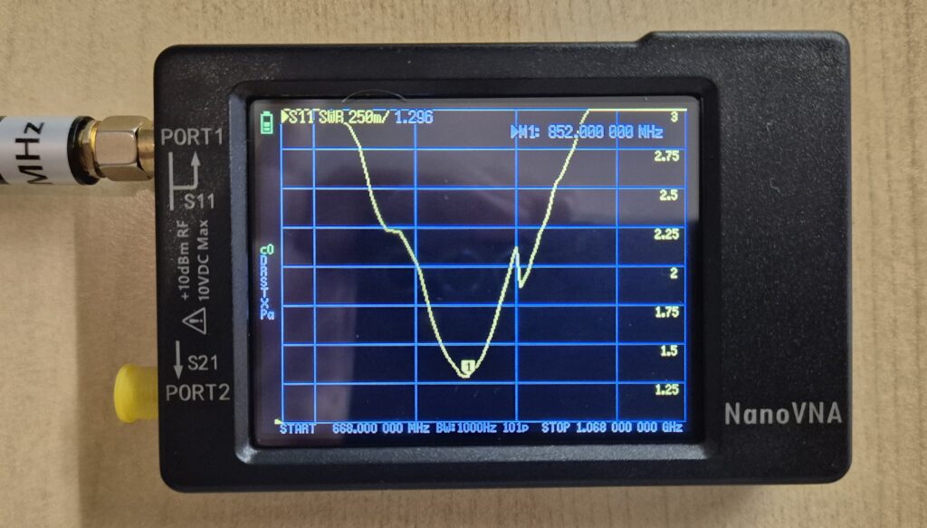
What we’re looking for is the minimum point of the SWR curve. That point indicates the frequency at which the antenna is resonating. Ideally we want:
- That minimum to be at 868 MHz or very close to it
- The SWR value at that point to be as close to 1 as possible
Comparison example
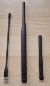
In this comparison I’m going to test three different antennas that came bundled with various Meshtastic and MeshCore device kits. None of them were purchased separately, they’re the kind of antennas that most people end up with after buying a few development boards or starter kits, and that usually end up in a drawer without anyone really knowing how well they actually perform. That’s exactly what we’re here to find out. From left to right: Antenna A, B, and C in the photo below.
| Antenna | Best SWR Frequency | Minimum SWR | SWR at 868 MHz | SWR at 915 MHz |
|---|---|---|---|---|
| Antenna A | 852 MHz | 1.296 | 1.323 | 2.016 |
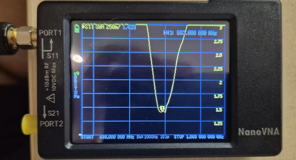
| Antenna B | 892 MHz | 1.290 | 1.980 | 2.020 |
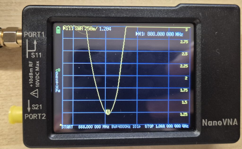
| Antenna C | 808 MHz | 1.204 | 2.900 | 4.000 |
Antenna A is the best option for use at 868 MHz. It resonates at 852 MHz — only 16 MHz below the target frequency — and at the working frequency has an SWR of 1.323.
Antenna B resonates slightly above 868 MHz (at 892 MHz), but its SWR at 868 MHz is 1.98 — below the 2:1 threshold generally considered acceptable in RF. It should perform well in the field, though with slightly less efficiency than the previous one. Interestingly, at 915 MHz it reads 2.02, almost identical — which confirms its resonance sits right between the two bands, not perfectly optimized for either. As its label suggests, it’s an antenna designed to cover both the 868 MHz and 915 MHz ranges.
Finally, Antenna C is the worst performer: its actual resonance is at 808 MHz, and at 868 MHz its SWR is 2.9 — pushing the edge of what most consider acceptable.
Other parameters that matter
SWR and resonant frequency are the most accessible measurements for a quick antenna evaluation, but there are other parameters that determine how an antenna actually behaves in the field. Most of them are found in the manufacturer’s datasheet rather than measured with a NanoVNA, for example:
- Maximum input power: The maximum RF power the antenna can handle without being damaged.
- Gain (dBi): How much the antenna concentrates power in a given direction.
- Radiation pattern: The shape of the antenna’s coverage in 3D space.
Is a NanoVNA worth it?
If you spend any amount of time with mesh networks or amateur radio, the short answer is yes. For under €50 you get a tool that takes you out of the guesswork. In my case it saved me from continuing to test in the field an antenna that simply wasn’t resonating well at 868 MHz — and it confirmed that another one that looked generic was actually performing really well.
It’s not an everyday tool, but when you need it, there’s no substitute.
Which NanoVNA should you get?
If you’re just starting out, the recommendation is clear: the NanoVNA-H. It’s the one I own and the one with the most community support. The differences compared to the original are significant — better quality touchscreen, frequency range extended up to 1.5 GHz, and better measurement stability. If you need to reach up to 4 GHz there’s the H4, though for most mesh network use cases that’s an unnecessary step up.
For Meshtastic and MeshCore applications at 868 MHz, the NanoVNA-H is more than enough. The jump to the H4 only makes sense if you’re also working with 2.4 GHz bands or higher, such as WiFi or some LoRa variants.