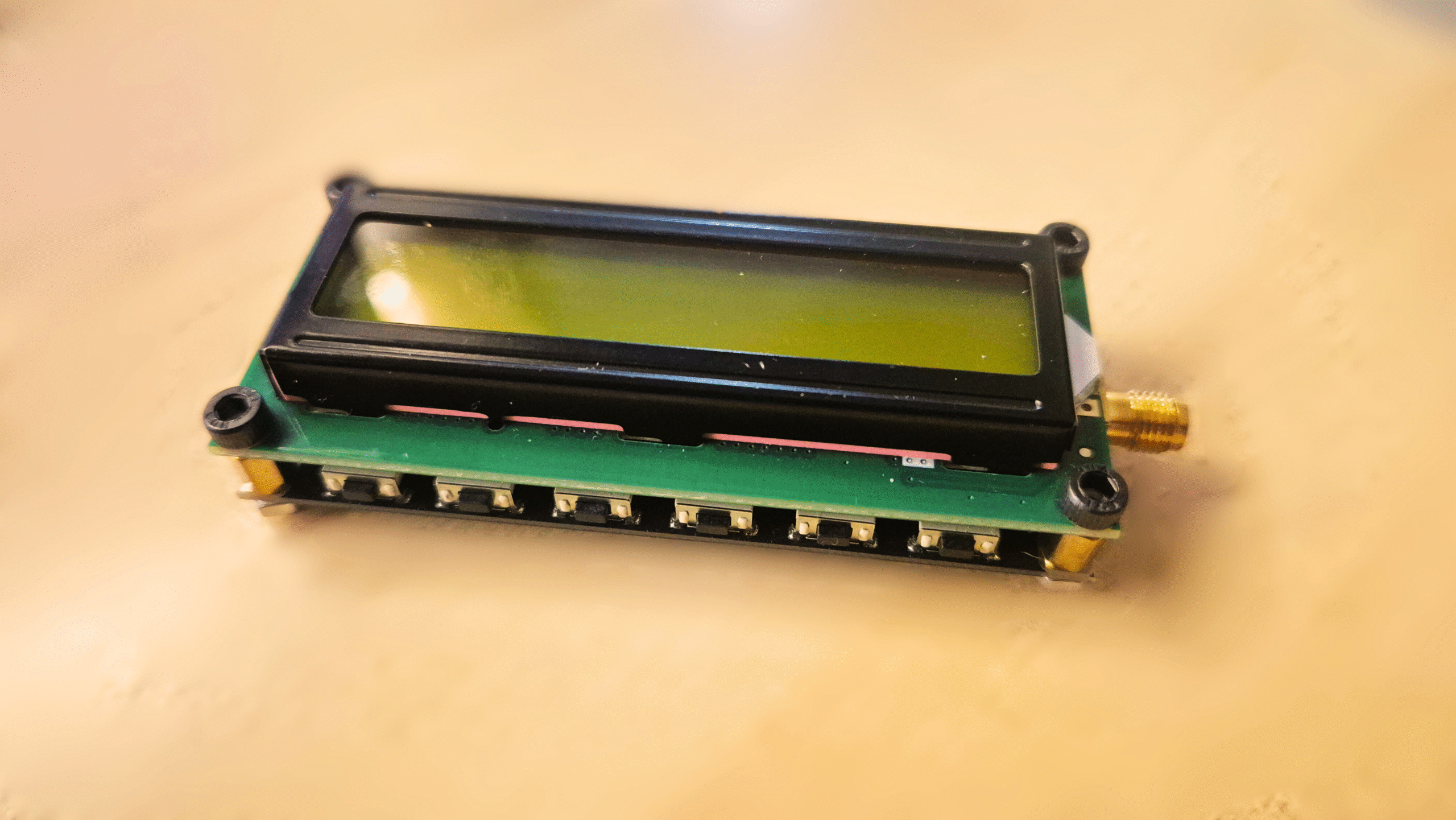
The AD8319-Based Power Meter
This RF power meter is based on the AD8319 chip (I recommend this model, as it allows up to 8 GHz), which is more than sufficient for my lab needs. It allows me to measure within frequency ranges from Bluetooth and Wi-Fi signals to BLE from microcontrollers like the ESP32 (2.4 GHz or 5GHz), and even various ranges used in video transmission systems.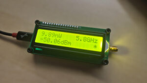
RF POWER METER: [link]
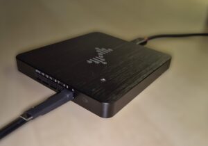
The device itself is very straightforward: it features a USB Type-C connector for power, an SMA female connector to attach the RF equipment we want to measure, and a display to show real-time power measurements in both Watts and dBm. The menu allows us to configure the target measurement frequency (900MHz, 1.9GHz, 2.2GHz, 3.6GHz, 5.8Ghz y 8GHz).
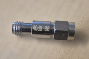
The main drawback of this power meter is its extreme susceptibility to overload. The safe power input limit is very low, not exceeding +5 dBm (approximately 3.16mW). This power level is quite small, and we can easily exceed it when trying to measure equipment like a VTX (Video Transmitter used on drones for amplified video transmission). Therefore, we must use RF attenuators to decrease the power entering the meter, thereby protecting the equipment from damage.
For example, in practice, I use it to validate the performance of my drone and check the power output of my VTX to make sure everything is correct. My VTX model is a Rush TankV2, which has various power modes:
25mW — 14dBm
400mW — 26 dBm
800mW — 29 dBm
1.5W — 32 dBm
Since we can’t observe this equipment without a load, it will be useless, even if the lowest transmission power is below the 3.16mW limit. This is why we must rely on attenuators.
How to Select Attenuators for VTX Measurement
To determine the minimum required attenuation, we must consider the expected maximum power (Pmax) and subtract the safe limit of the meter (P_safe). The formula for the minimum attenuation A_min in dBm is:
For instance, to measure 800mW (29dBm), keeping in mind that the maximum safe limit is +5dBm, we must use an attenuator of at least 24 dB(29dBm- 5dBm). Considering that it will be difficult to find a 24 dBm attenuator, choosing a 30dBm attenuator will be more than sufficient to measure this type of RF power.
Completing the rest of the measurements, the recommended attenuators are:
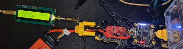
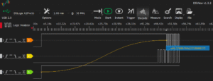
To finish, I attach some of the tests I conducted and the results obtained in the RF power measurements of the drone’s output. Specifically, I present the comparison between the expected output levels of my VTX Rush Tank V2 and the measured power values
![]()
As shown in the image, the VTX is transmitting in Yellow Mode, which according to the datasheet is around 400 mW. Because I’m using a 40 dB attenuator, the power meter reads -13.65dBm.
-13.65dBm + 40dBm (Attenuator) = +26.35 dBm, which corresponds to 430mW, close to the expected rf power.
I hope you enjoyed this post. Let me know what you think and if you’d like to see more related content.