
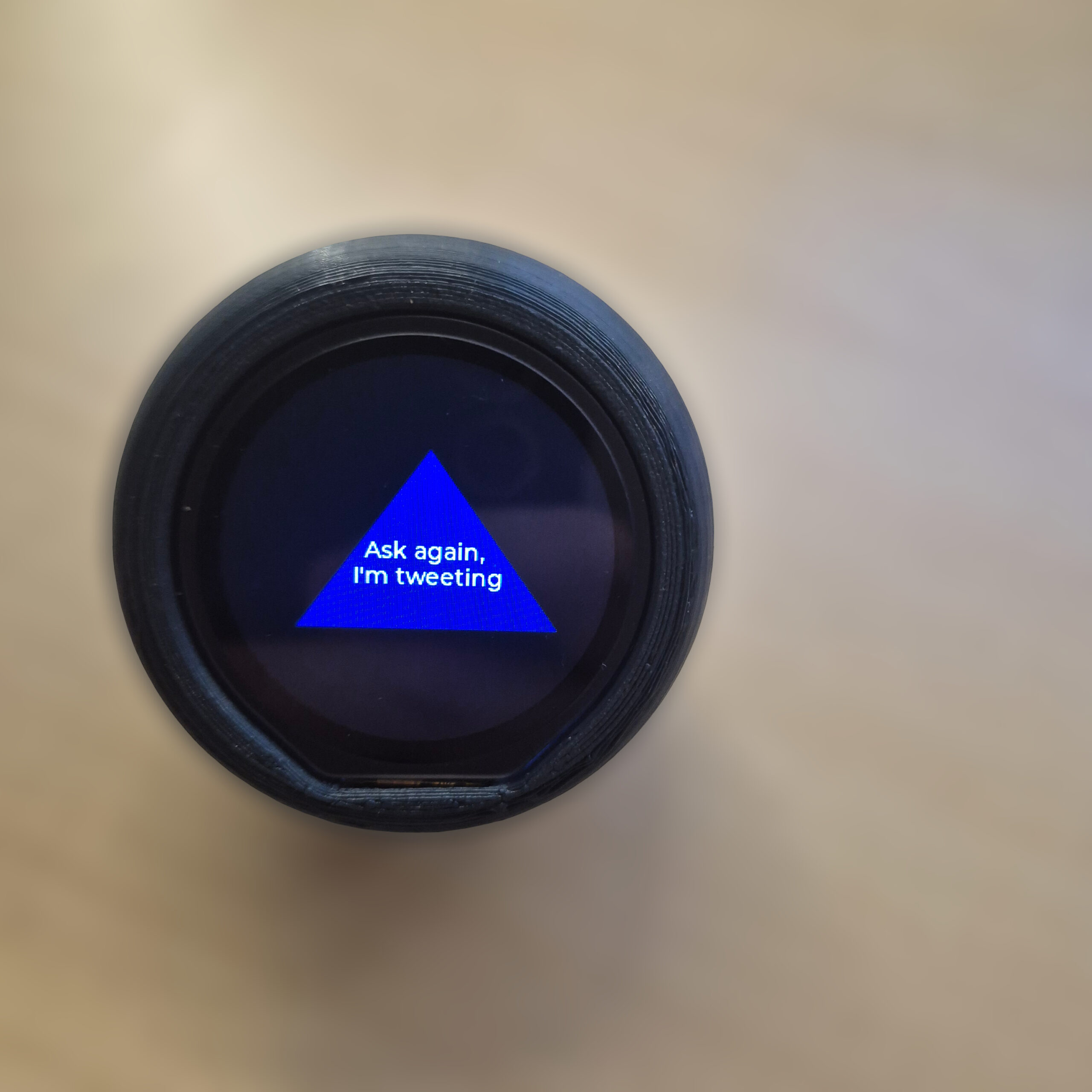
Over the last few weeks, I’ve been experimenting with round LCD displays to see what they can really do. The moment I held one in my hand, I had a total Toy Story flashback: Woody asking the Magic 8-Ball for advice.
I never actually owned one as a kid, so I thought… why not build my own? But let’s take it a step further. Instead of the classic cryptic answers, why not get advice from Elon Musk, Clint Eastwood, or your favorite celebrity? That’s how the RP2350 Magic Ball project was born
For those who don’t know, the Magic Ball was invented in 1946. It is a ball with the appearance of a billiard ball containing an icosahedron floating in liquid. This icosahedron has answers on its faces like yes/no/maybe. The system works in such a way that you ask the ball a question while shaking it; once formulated, you look at the bottom and see one of the sides of the icosahedron with the answer to your question.
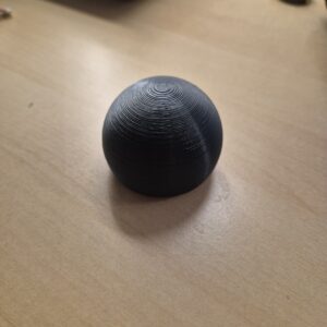

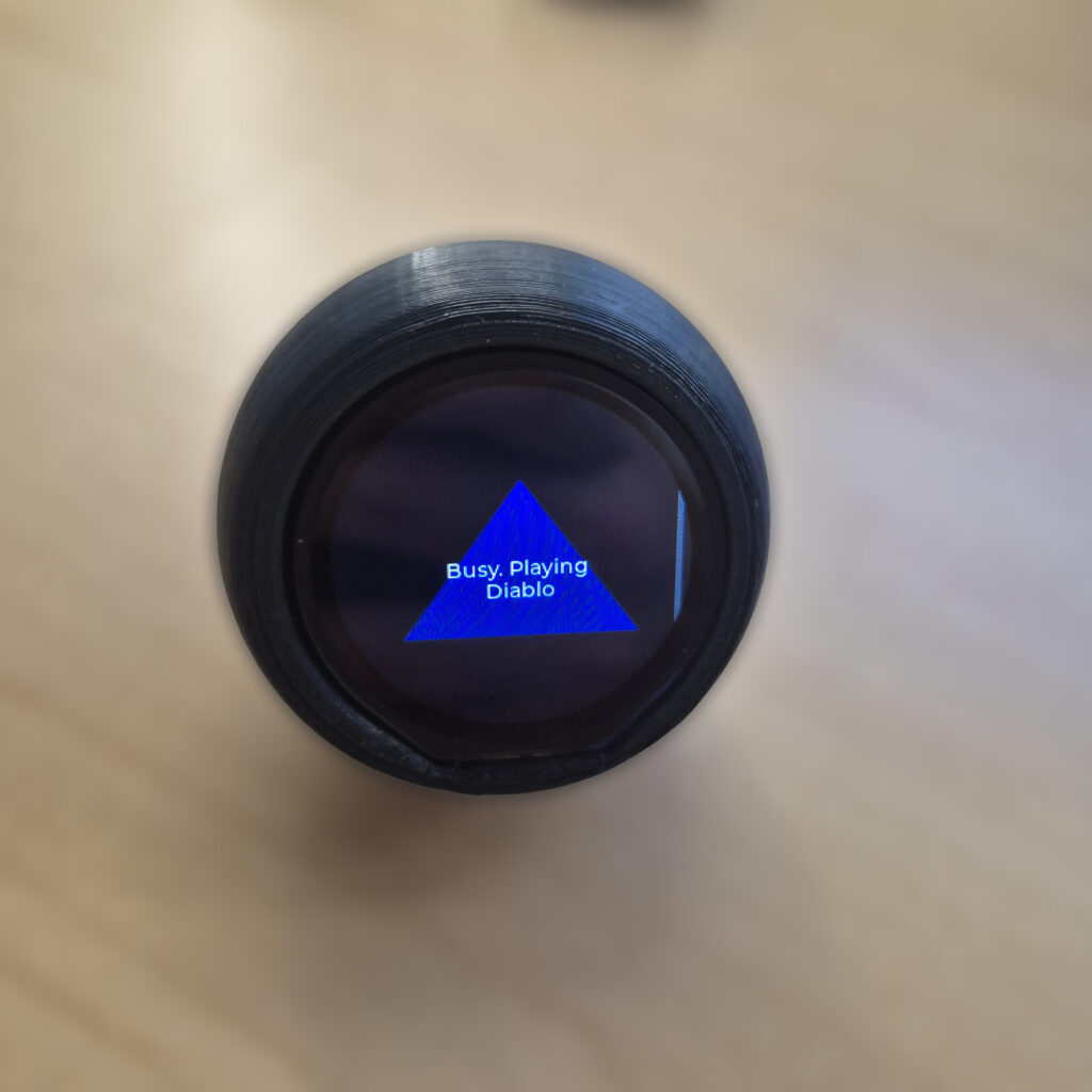
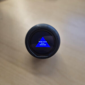
Table of Contents
Toggle1. HARDWARE
This is the list of materials I used for this project:
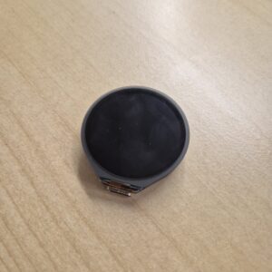
It is a module with a 1.28-inch LCD touch display (though the touch feature is not used for this project) with a resolution of 240×240. Regarding sensors, it incorporates a gyroscope and a temperature sensor.
This module is programmable thanks to its RP2350 microcontroller, the famous chip developed by Raspberry Pi included in its Raspberry Pi Pico series (Dual Core ARM Cortex M33), whose oscillator can run up to 133MHz.
Lastly, it features an integrated circuit to connect a 4.2V battery and charge it via a USB connector, as well as 6 free GPIOs through its SH1-0 connector. It is easily programmable using the Arduino IDE, MicroPython, or the Pico C/C++ SDK.
Additionally, on its official website, there are several examples and guides on how to make it work using either its own graphics library (handling its GC9A01 controller and the CST816S touch driver) or the LVGL library, which facilitates the creation of advanced graphical interfaces (focused on creating buttons, sliders, graphics, animations, etc.). https://www.waveshare.com/wiki/RP2350-Touch-LCD-1.28#Supporting_Resources
3.7V/4.2V Li-Po battery with MX1.25 connector

3. Enclosure
Custom 3D print designed in Fusion 360.
2. SOFTWARE
Although the module allows for advanced interfaces, I decided for the LVGL library to manage the graphics. The main challenge was not aesthetic, but logical: How to simulate a 3D die without dying in the attempt?
One of the requirements for my software was to simulate what happens in the original balls: the die can move across the display without necessarily changing the message. On the other hand, if shaken hard enough, a different message should appear. Because of this, you must detect smooth movements to simulate the die’s floating motion, while abrupt movements simulate a change in the message.
For the icosahedron message simulation, I didn’t want a system where a random face was printed simply upon detecting sudden movement. Simulating 3D geometry with its rotation matrices would be costly for the microcontrollers.
My goal was to create a menu or navigation system over an icosahedron (20 faces), where the user could move infinitely between adjacent faces, guaranteeing:
Reciprocity: If A is a neighbor of B, B must be a neighbor of A.
Zero “blind spots”: There can be no invalid states.
Computational cost O(1): The state change must be instantaneous.
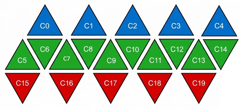
Instead of calculating adjacencies at runtime, I “flattened” the icosahedron into a static data structure (Look-Up Table), much like making a paper figure. I defined the icosahedron as a graph of 20 nodes, where each node has exactly 3 edges and can connect through them to its neighbors in the following three fixed logical sectors:
Sector 0 (Vertical): Connects to the “base” of the triangle.
Sector 1 (Left): Connects to the left side neighbor.
Sector 2 (Right): Connects to the right side neighbor.
The layout follows the actual geometry of the solid:
North Pole: 5 faces, all with the same orientation (▲).
Equatorial Belt: 10 faces, alternating orientation: ▲▼▲▼▲▼▲▼▲▼ (this is real and geometrically correct).
South Pole: 5 faces, all with the opposite orientation to the north pole (▼).
typedef struct {
    int neighbors[3];  // 0: Vertical, 1: Left, 2: Right
    int orientation;   // 1 = ▲, 0 = ▼
    int msg;           // Index of the associated message
} Face;

Face icosahedron[20] = {
    // North Pole (Blue)
    {{5, 4, 1}, 1, 0},    // Face 0
    {{7, 0, 2}, 1, 1},    // Face 1
    {{9, 1, 3}, 1, 2},    // Face 2
    {{11, 2, 4}, 1, 3},   // Face 3
    {{13, 3, 0}, 1, 4},   // Face 4

    // Belt (Green)
    {{0, 14, 6}, 0, 5},   // Face 5
    {{15, 5, 7}, 1, 6},   // Face 6
    {{1, 6, 8}, 0, 7},    // Face 7
    {{16, 7, 9}, 1, 8},   // Face 8
    {{2, 8, 10}, 0, 9},   // Face 9
...
3. 3D PRINTING
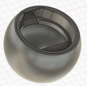
For the 3D printing, I used Fusion 360. Initially, I thought about making a two-part sphere to open and close it to access the hardware, but it seemed to add too much complexity, and I didn’t trust how a threaded closure would turn out with the 3D printer.
So, I went with my second option: making it a single piece based on a hollow sphere. By making a transversal cut, the resulting plane is shaped to fit the display, so that we insert the battery first and then the display. The display rests on a plane so it stays at the perfect height without sinking in. For fixing it, you can use double-sided tape or even hot glue, which can be applied to the PCB without risk as it is non-conductive.
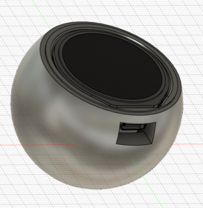
Since this module allows a USB connection, you have to account for that when adding the opening; it can be complex to visualize where to position the USB slot. In my case, I recommend that if you ever need to do something like this, look for the .step models of the boards to insert them into your designs and see how the fit looks. This also allows you to see if you are making errors before wasting time printing the part.
4. CONCLUSION
Do you want to try the RP2350 Magic Ball? Click the following link to send me an email, and I will send you the binary (.uf2) ready to flash with Elon Musk’s most famous quotes.
If you’re interested in a version with personalized phrases (friends, family, or your own brand), you can contact me to request a custom build.
What did you think of this approach to simulating 3D geometry? Leave a comment below, I would love to read your ideas!