
This post belongs to the series of posts about the Meshtastic Build Off 2026. The previous posts are:
- https://myembeddedstuff.com/meshtastic-build-off-2026-retromeshdevice
- https://myembeddedstuff.com/meshtastic-build-off-2026-pcb-assembly
Once I had the PCB assembled, the next step was to verify that everything was actually working as expected.
At this stage, I did not want to jump straight into the Meshtastic integration. Even though that was the ultimate goal of the project, it seemed more intelligent to validate the hardware in isolation first. When you are booting a board for the first time, separating hardware and firmware issues usually saves a lot of headaches.
I am going to split this post into two sections. First, why I consider it necessary to create a simple firmware to validate the board and how to do it. Second, an analysis of the device’s power consumption using measurement tools to characterize my board. This last point can give you plenty of details on whether you missed something in your design.
Table of Contents
ToggleFirmware Validation
My recommendation is simple: before integrating any complex firmware, create a test firmware that is as small and controlled as possible.
This applies whether you assembled the board yourself or if it came pre-assembled from the factory. In both cases, issues can appear:
Cold solder joints
Misaligned components
Pins without continuity
Assembly errors
Or even small manufacturing defects
In my case, this was especially important because a large part of the assembly was done manually as I explained in the previous post.
Test Firmware for Validation
For this initial validation, I developed a small firmware in ESP-IDF whose sole purpose was to verify that each hardware block responded correctly.
The firmware is available in the following repo: https://github.com/myembeddedstuff/RetroMeshDevice
The idea was simple: cycle through every single peripheral one by one and verify that each subsystem worked as it should. This included:
Buzzer
ADC battery reading
I2C bus (MCP23017 and OLED display)
T9 Keypad
Rotary encoder
SPI bus (LoRa SX1262 module)
Interrupts
To develop this validation firmware, I leveraged AI as a support tool. Instead of writing the initialization code for the GPIO, ADC, I2C, or SPI completely from scratch, I prepared a prompt detailing the schematic of the board, the pins used, and the exact order of the tests I wanted to run.
This allowed me to very quickly generate a functional baseline to work from. The key takeaway here is not delegating the entire development process, but using AI to accelerate “low-value” tasks, especially for temporary firmware where the only goal is to validate hardware.
The generated implementation usually requires some adjustments—particularly regarding specific ESP-IDF details, peripheral configurations, or things that might not adapt 100% to what you want—but it still drastically reduces the time needed to get a working first version.
I prefer to invest my time in the final product firmware, where the architecture and robustness are truly critical, and use tools to speed up more mechanical phases like the initial bring-up.
PROMPT:
Act as an expert embedded systems engineer and generate a hardware bring-up validation firmware suite for the ESP32-S3 target using strictly ESP-IDF v6.0. The hardware configuration is a custom PCB based on a Seeed Studio XIAO ESP32-S3 Plus module. Do not use any legacy or deprecated APIs.
The firmware must follow a table-driven test runner structure where each test case returns a status of PASS, FAIL, or SKIP. Every intermediate result and the final execution report must be mirrored simultaneously to the UART console and to the OLED display. All interactive user tests must include an explicit timeout constraint to prevent the validation pipeline from hanging indefinitely, marking the test as SKIP if the timer expires.
Write the codebase implementing the following exact sequence of numbered tests:
Buzzer: Assert the digital output pin low for 500ms, then launch an interactive terminal prompt asking the user if the audible beep was heard.
Battery ADC: Drive the
VBAT_SENSE_ENpin high, wait for the circuit node voltage to settle, collect N averaged raw analog readings, apply the curve-fitting calibration scheme along with the resistor voltage divider ratio, and immediately disable theVBAT_SENSE_ENpin. Return PASS if the calculated battery voltage falls within[3.0V, 4.3V]; otherwise, return FAIL and output the raw sample metrics.I2C Check: Scan the I2C bus for connected devices and verify the presence of both the OLED display and the MCP23017 I/O expander by detecting their expected slave addresses. Report the detected devices and return PASS only if both peripherals are successfully found; otherwise, return FAIL indicating the missing device(s)
T9 Keypad Sequential Walk: Prompt the user to press each key by name in a predefined sequential order, applying a key timeout. Return FAIL on timeout, but include a dedicated bypass key configuration to skip all remaining keypad interactions.
SPI Link to SX1262 LoRa Transceiver: Send the
GetStatus (0xC0)command byte and validate that the response payload is neither0x00nor0xFF(both indicate a dead or floating bus connection). Decode and print the chip’s current operational mode field in a clear text description.Interrupt Line Validation: Monitor the physical ESP32 GPIO pin tied to the bridged INTA/INTB lines of the MCP23017 and validate that the signal line toggles states properly when an interrupt event is physically triggered or simulated.
Upon completing the execution suite, generate a clean summary table showing the total counts of PASS / FAIL / SKIP events along with the explicit name of every failed test case, printing this final report block to both the UART console and the local OLED display.
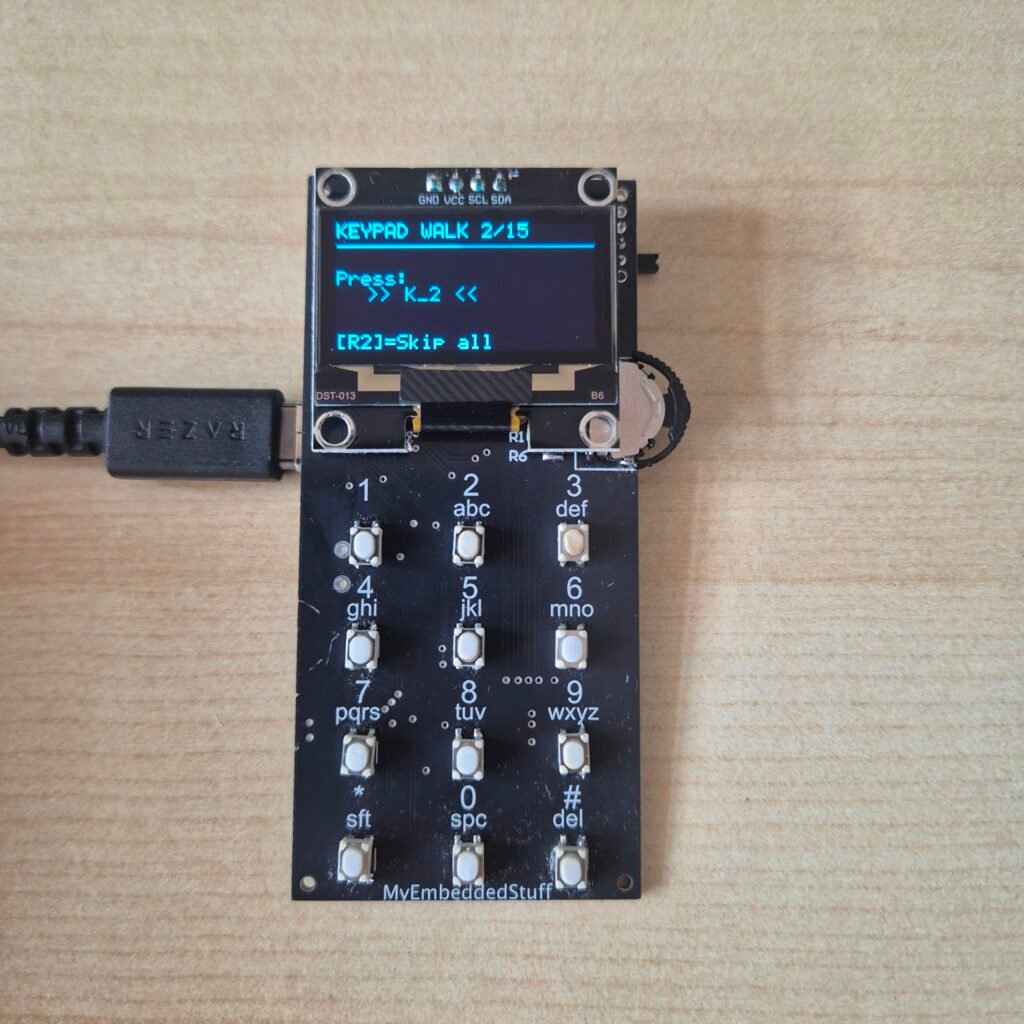
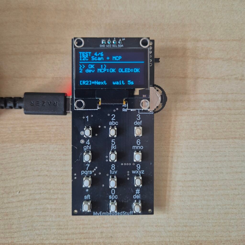
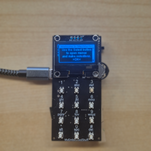
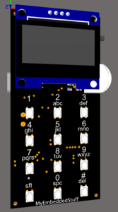
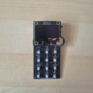
Once the test firmware was generated, all that was left for me to do was test that everything was correct and make a few small adjustments. I am attaching some photos of the process so you can see the result.
Power Consumption Analysis with PPK2
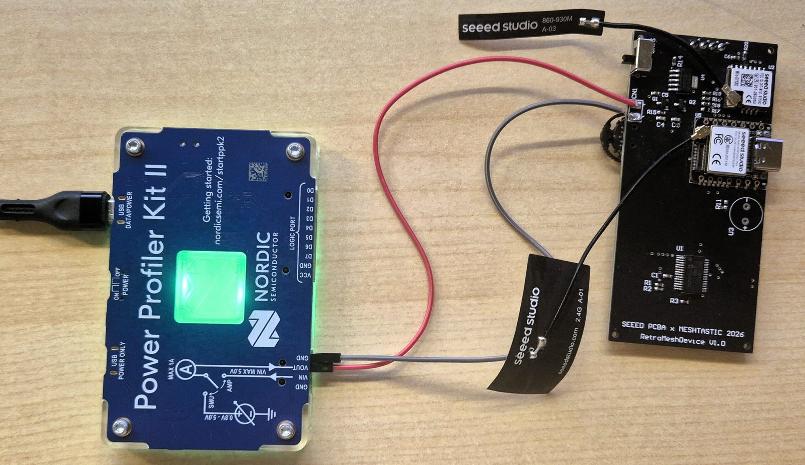
The next step, once all connections were validated, was to measure the device’s power consumption in different modes. This is incredibly useful not only for characterizing your board’s power profile but also for spotting high consumption peaks that might indicate something is wrong.
To measure the power consumption, I used the Power Profiler Kit II from Nordic Semiconductor, commonly known as the PPK2.
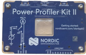
If you do not have it in your lab and you work with embedded hardware, I recommend it without hesitation. It is one of those tools that once you use it, you do not understand how you lived without it.
Its price is quite reasonable for what it offers. It gives you two features in a single device: a configurable power supply from 0V to 4200mV, and a real time power analyzer with a minimum resolution of 100nA. You can also connect several GPIOs to correlate consumption peaks with specific firmware events, which is extremely useful when you want to understand exactly what is happening at any given moment.
The accompanying software, nRF Connect for Desktop, is simple and intuitive. You can select time ranges, zoom in on specific peaks, and view the average, maximum, and minimum consumption of each section. For the type of analysis I needed in this case, it was more than enough.
First, I connected my device running the already functional Meshtastic firmware (spoiler: I have already validated Meshtastic running and wanted to include it to see its power profile on this post). I observed that the consumption is around 75.56 mA with the OLED screen turned on and the device actively in use.
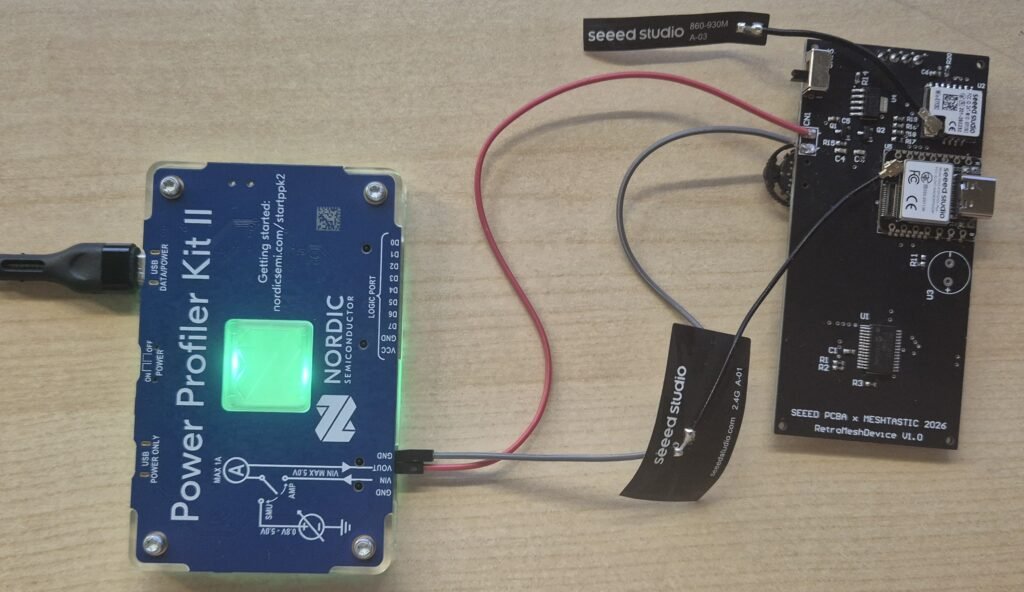
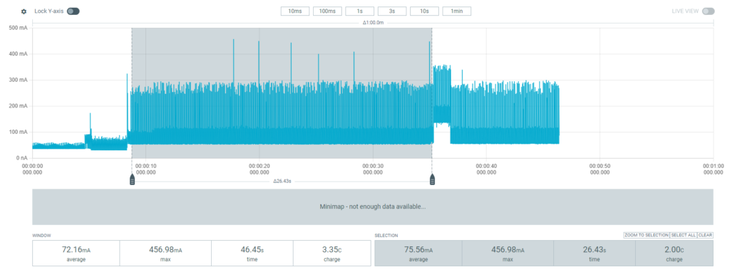
Looking at the following graph, we can observe some consumption peaks when transmitting packets. The current draw rises up to 191.76 mA, but this happens for a very short period of time, meaning that the consumption that will most characterize the device is 75.56 mA.
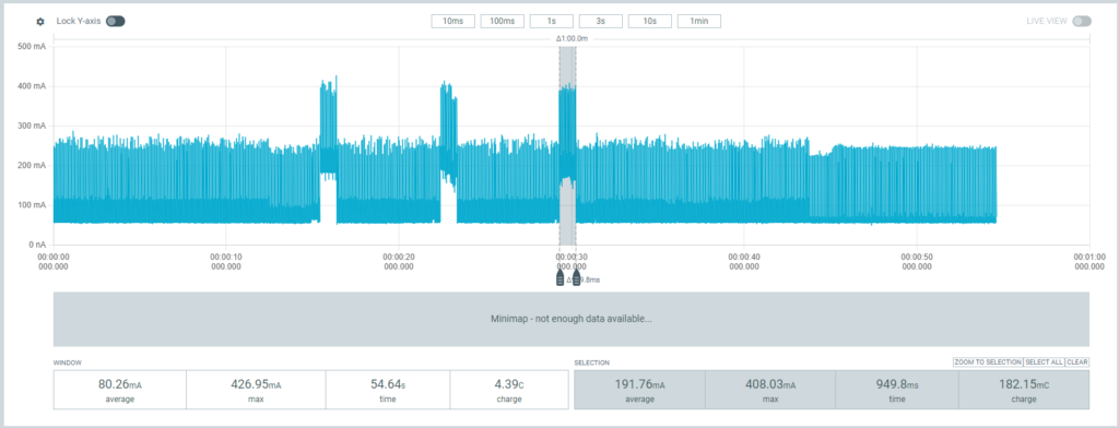
When the device is turned off, I also wanted to see how much power it consumed. Therefore, in the following graph, you can observe that when I turn off the slide switch, its consumption drops down to 290.78 uA.
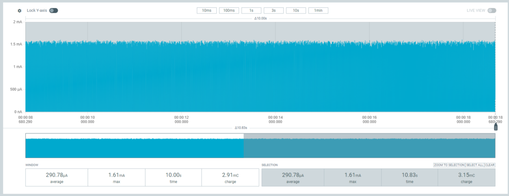
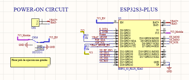
This is one of the things that has been giving me headache. A 290 uA draw while the slide switch is turned off. Considering that the ESP32S3Plus module is in reset and the 3V3 rail that powers the rest of the modules (LoRa module, OLED, buzzer, etc.) is not even being generated, this is a very high consumption. In theory, the ESP32-S3 should consume around 1 uA in power-off mode.
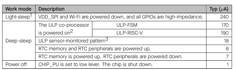
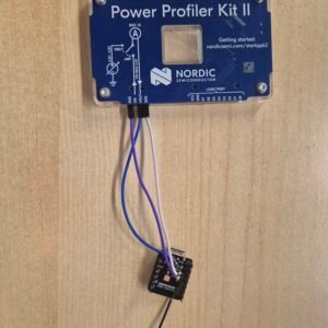
Having a not assembled XIAO ESP32-S3 on hand, I decided to solder some wires directly to it and measure its standalone consumption to check if there was a flaw in my design. However, as you can see in the following graph, the consumption was 198.89 uA. It is slightly less, but still a high enough consumption to confirm that the XIAO module itself was already drawing nearly 200 uA while held in reset.
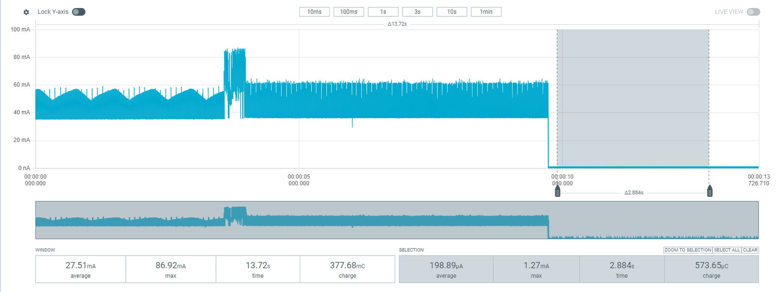
I wrote to the manufacturers (SeeedStudio) of the XIAO module to see if they could explain the reason behind this. Their response was very quick and cleared it up for me. This behavior is necessary because there is an internal pull-up resistor that allows the module to boot without needing to connect the reset pin, while also complying with the timing constraints specified by Espressif.
This is a 10kΩ resistor, which means that at 3V3/10k -> 330 uA aprox, a value that, depending on component tolerances, might vary slightly from board to board.
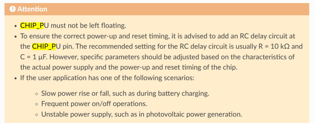
Perhaps a Power-On Reset (POR) IC to ensure the power supply is stable before enabling the reset line could do the trick. However, that would mean modifying the inside of the XIAO module itself, which would require removing the Faraday cage—something that can get way too complicated.
At the end of the day, it is a high consumption, but in the following table you will see that with standard batteries, the battery life in power-off mode will still last for more than half a year. I would not modify it.
| Device State | Measured Consumption | Duration (1000mAh Battery) | Duration (2000mAh Battery) |
|---|---|---|---|
| In use (Meshtastic + OLED + BLE) | 75.56 mA | ~13.2 hours | ~26.4 hours |
| Power Off (Base draw) | 0.290 mA | ~3448 hours (~143 days) | ~6896 hours (~287 days) |
Conclusion
The 290 µA standby draw is probably the thing that ate most of my debugging time on this build. My first assumption was that I’d screwed up the design, as an ESP32-S3 in reset should pull around 1 µA, not 290. So I isolated the module and soldered wires to a bare XIAO, similar consumption. Not my PCB.
Wrote to Seeed and I got a real answer fast: an internal pull-up on the EN pin, needed for a clean boot without an external reset line, per Espressif’s timing spec. 3.3V over 10kΩ ≈ 330 µA, which matches my measurement within tolerance.
Is it worse than a theoretical reset? Sure. But put it in context: on a 2000mAh cell, this thing runs a full day of active use, and powered off, it’ll sit for over half a year before you’re anywhere near a dead battery. That’s plenty for how this actually gets used.
On the AI-for-bring-up-firmware thing: still stand by it. Good for throwaway validation code, not for anything I’d ship. Save the real engineering time for the production firmware.
Side note for anyone designing from scratch: Seeed’s new XIAO nRF54LM20A (Sense) has an actual System OFF state via their pads, so you can skip the 290 µA headache. It doesn’t help the RetroMeshDevice since Meshtastic doesn’t support it yet, but worth knowing about if you’re not locked into ESP32.
Note: If you like this content and project, please consider giving a like to the following GitHub issue where I discuss my latest progress. I am currently participating in the BuildOff, and your support would mean a lot! https://github.com/Seeed-Projects/meshtastic-build-off-2026/issues/10
Pingback: Meshtastic Build-Off 2026 - Meshtastic firmware implementation - myembeddedstuff.com