
The new Arduino Uno Q marks a turning point for Arduino’s product line following its acquisition by Qualcomm. In this post, I will discuss why this board is so significant, what it is composed of, and future lines.
Table of Contents
ToggleDescription
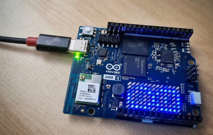
Following Qualcomm’s acquisition of Arduino, we have seen a shift in their designs. The new Arduino Uno Q maintains the original Uno form factor, but its internal components are completely different: the famous ATmega chips have been left behind in favor of a totally new architecture.
Architecture
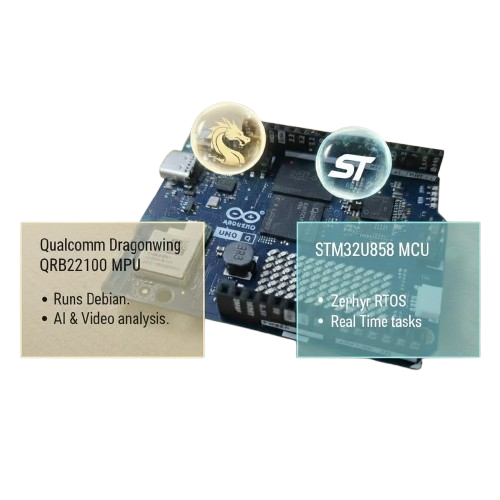
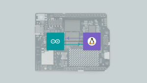
They have opted to assemble a high-performance MPU chip, the Qualcomm Dragonwing QRB2210, alongside a MCU the STM32U585 microcontroller. This brings it closer to the concept of an SBC (Single Board Computer), allowing the MPU to run an operating system like Debian Linux for AI tasks or video analysis, while the MCU handles critical real-time processing.
Although it has been criticized for moving away from the simplicity that made Arduino famous, after a few days of use, I find it to be a bold and very useful proposal for projects that require power without sacrificing the learning experience. This is a new product line; I don’t believe it will replace the basic boards, but rather expand the possibilities. Using the Arduino Uno Q is not complex, but it is a different concept. And perhaps one of the most complex parts: the communication between the MPU and MCU, has been resolved in a very simple way.
It is important to note that the MPU has high power consumption. By using Debian, we gain networking and multitasking capabilities, but we lose determinism (the ability to respond within an exact timeframe). Therefore, the combination with an MCU running Zephyr RTOS is key: it responds to real-time constraints and can monitor tasks without consuming MPU resources.
Interfaces
Regarding the hardware, the pins are divided. Those connected to the MCU manage interfaces such as SPI, I2C, and UART to interact with external modules in real-time.
On the other hand, the LED matrix and the Wi-Fi/Bluetooth module are linked to the MPU (Debian), although mechanisms exist for the MCU to perform network tasks through the “Bridge.”
Top side
When we look at the traditional Arduino headers, located on the top side of the board, we can see that all of them are connected to the MCU, as their main purpose is the same as in a classic Arduino: providing SPI, timers, UART, and similar interfaces.
Since these signals are labeled as PAx, PBx, PCx, they correspond to native MCU pins (STM32).
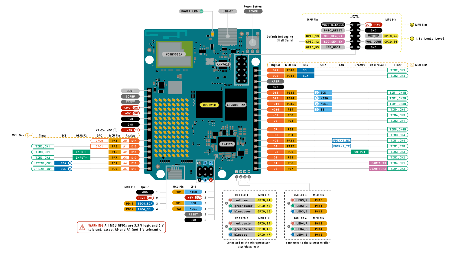
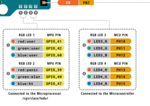
In addition, for debugging purposes, the board includes two RGB LEDs controlled by the MCU, as well as two additional RGB LEDs controlled by the MPU, which are accessible through /sys/class/leds.
Back side
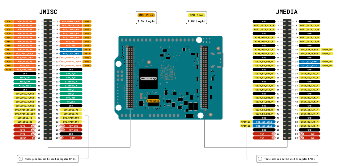
However, if we look at the back side of the board, we find two additional connectors (they do not use a 2.54 mm pitch): one labeled JMISC and another labeled JMEDIA.
- On the JMISC connector, both MPU and MCU signals are exposed (remember that MCU signals are identified as PAx, PBx, PCx, etc.).
- On the other hand, JMedia is fully related to the MPU.
It is important to note that MPU-related signals operate at a 1.8 V logic level, so special care must be taken when using them in order to avoid damaging the device.
Programming and Workflow
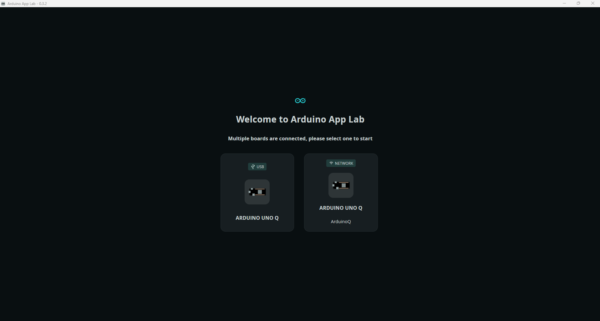
Programming and board usage are primarily performed with the new ArduinoAppLab application. Once the board is powered and the application is launched, we can connect either via USB or, if it is connected to our network, via Wi-Fi.
Once we access the board, we will be able to:
Develop our own applications under the MyApps section.
View example models with pre-created applications for various purposes.
Explore Bricks, which are specialized applications that can complement our own apps.
Connect to our board via shell.
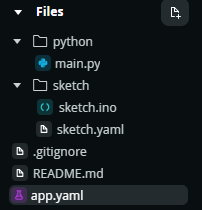
We can see the applications in the MPU path under the directory /home/arduino/ArduinoApps. Each app follows this structure:
/python: Houses the scripts that run on the MPU (Linux).
/sketch: Programs for the MCU (STM32), written as the usual “sketches.”
When running our applications, the logic described in the Python script will execute on the MPU, while the .ino sketch will run on the MCU. Each operates independently, focusing on its respective tasks.
However, in most cases, we will want them to communicate to notify each other of certain actions. This is why a communication system based on RPC has been developed, but this will be explained in another post.
Conclusion and future lines
The Arduino Uno Q represents a paradigm shift compared to previous releases. After analyzing its architecture and communication system, I must say that it remains quite accessible for those with less experience in the field. Unlike many SBCs, the board comes ready to work right out of the box, and they have successfully streamlined complex components to keep them simple.
It should be viewed as a new product line focused on more complex applications, designed to meet different needs rather than replace what came before. It remains accessible, and I believe it has significant room for evolution.
That being said, I would like to see certain aspects become more open. For example: how would the STM32 behave if we decided to use FreeRTOS? Could we generate Yocto-based distributions for the MPU?. I believe exploring these possibilities would open up new learning paths for this board.
I hope you enjoyed my analysis. In the next post I will talk about the RPC communication between MCU and MPU.
- Buy Arduino: Aliexpress link
- Buy Arduino: Arduino website
- More info: User guide Arduino Uno Q
Pingback: Arduino Uno Q Communication: A Deep Dive into RPC - myembeddedstuff.com
Pingback: Arduino Uno Q: The Truth About its Boot-Up Performance - myembeddedstuff.com
I am finding the Arduino UNO Q useful. Having never used Rpi much (or any SBCs), I don’t have much to compare it to, so having AppLab allow me to write Python and Arduino next to each other and easily launch a program (app) seems like a new thing in my mind.
The board did seem to get some initial “dislike”, but I suspect a lot of that was coming from people not liking that QualComm acquired Arduino, and not the merits of the board itself. Just my 2 cents 🙂 great article overview!