
Table of Contents
ToggleThe communication system
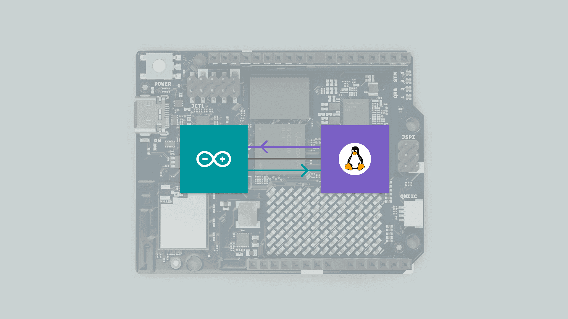
The Arduino Uno Q features a specialized communication method designed to handle data exchange between the MPU and the MCU. This system is based on RPC (Remote Procedure Call).
In this post, we will explore the architecture, the protocol, and a hands-on example of how to send and receive commands. We’ll even dive into a logic analyzer capture to see exactly how it works under the hood.
Before proceeding with this post, I strongly recommend reading my previous review of the Arduino Uno Q:
https://myembeddedstuff.com/arduino-uno-q-new-paradigm-review
RPC Description
Communication is based on RPC (Remote Procedure Call). This system operates like a sort of Router, hosted on the MPU as a service called Arduino-Router. It is responsible for creating and managing a connection table. This service receives requests from applications (both on the MPU and MCU) and redirects them to the subscribers of those requests, whether they are the MCU or different applications on the MPU.
Physical Layer: The system uses the UART interface.
MPU Side: Utilizes the
Serial1(typicallyttyHS1in Linux environments) driver.MCU Side: Utilizes its hardware
Serial1interface.Settings: The default baud rate is set to 115200 Bauds.
Methods
The system is managed programmatically through the BridgeClass. This class provides the essential methods to handle the lifecycle of the connection and data transmission:
begin(): Initializes the serial transport on the MCU and activates the link with the Router in Debian.call(method, args): Calls a function and waits for the result (synchronous).notify(method, args): Sends an instruction without waiting for a response; ideal for high-speed telemetry.provide(name, function): Exposes a function to be used by the system.provide_safe(name, function): Similar toprovide, but executes the function within the standardloop(). This is the secure option for usingdigitalWrite()or Arduino APIs without concurrency errors.
Protocol explanation
The system’s communication is based on the MessagePack communication protocol. The frame format is structured as a 4-element array:
[ type, id, method, parameters ]
Type: Indicates whether it is a Request (0), Response (1), or Notification (2).
ID (msgid): A unique 32-bit identifier used to pair each response with its corresponding request.
Method: A text string containing the name of the function to be executed (e.g., “digitalWrite”).
Parameters (params): A list (array) containing all the arguments required by the function.
Example:
MPU sends:
[0, 32, "ping", [1, true]](Request ID 32).In this case, 0 is the numerical value representing the message type (REQUEST), 32 is the ID, “ping” is the method name, and [1, true] are the parameters.
MCU responds:
[1, 32, null, true].This indicates ID 32, signaling that there was no error (null) and the result was true.
Real example
To validate the system, we set up a test environment:
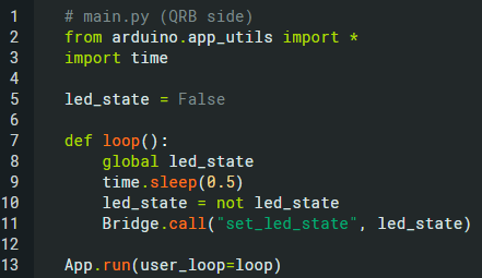
Python script: sends a bridge request "set_led_state", alternating between False and True.
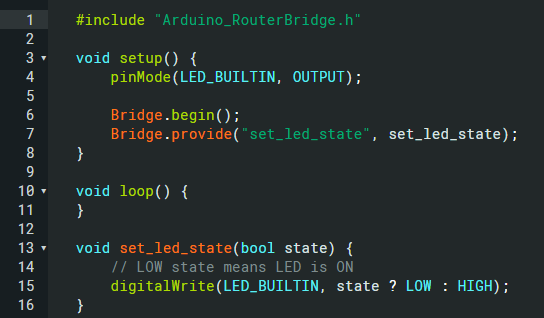
MCU sketch: receives the request and changes the LED state accordingly.
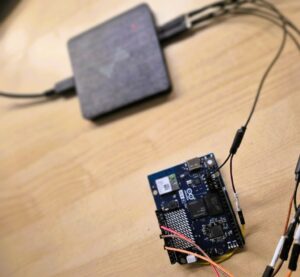
Using a logic analyzer connected to the UART TX/RX pins, we captured the binary flow at 115200 baud. Using the analyzer’s “Protocol Decoder” feature, we can inspect the raw hex bytes.
The logic analyzer used is the same as the one described in the following post.
WHY DID I START USING DREAMSOURCELAB LOGIC ANALYZERS?
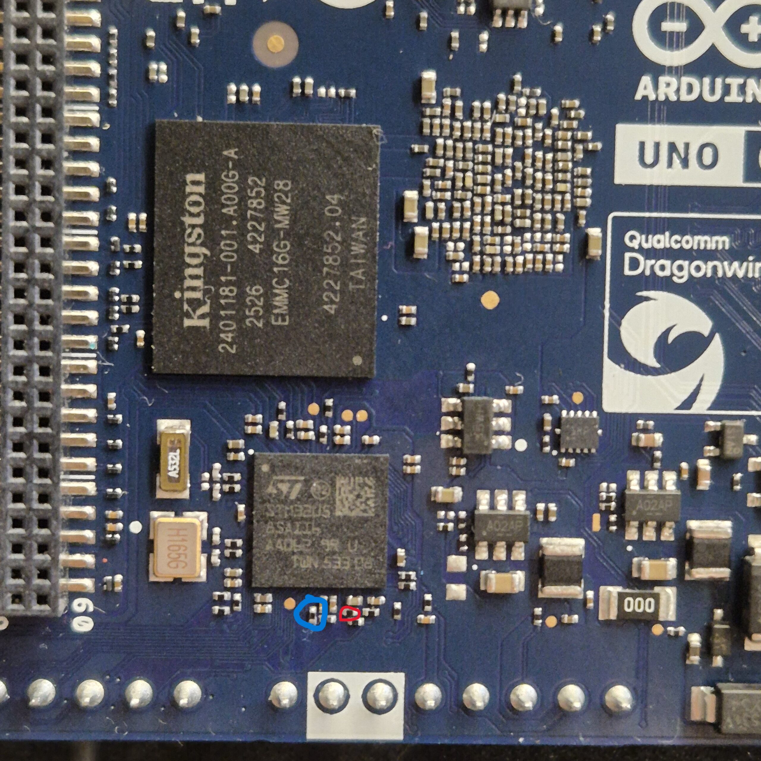
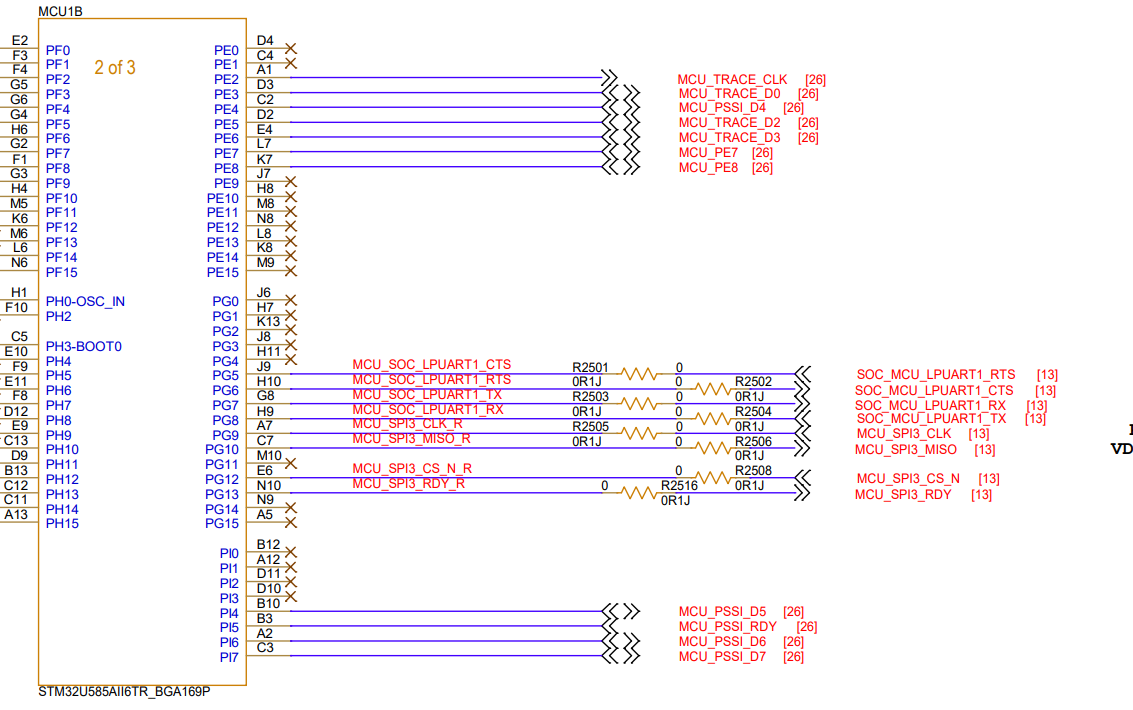
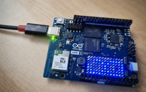
In the image below, the blue circle indicates the MCU transmission line, while the red circle shows the MPU transmission line. I located this setup through trial and error, since the exact connections were not immediately obvious. However, consulting the schematic revealed that resistors were present between the lines, which made it safe to sniff the communication. R2503 and R2504.
Captured data (MPU → MCU):
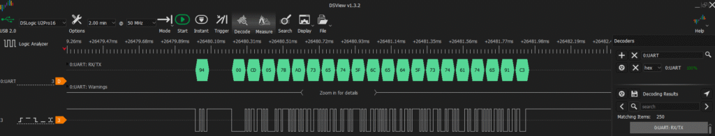
The analyzer captured the following hex sequence
94 00 cd 05 7a ad 73 65 74 5f 6c 65 64 5f 73 74 61 74 65 91 c2
94 00 cd 05 7b ad 73 65 74 5f 6c 65 64 5f 73 74 61 74 65 91 c3
94 00 cd 05 7c ad 73 65 74 5f 6c 65 64 5f 73 74 61 74 65 91 c2
By mapping this pattern against the MessagePack specification, we can decode the frame:
| Byte | Meaning |
|---|---|
| 94 | Header → fix array size 4 |
| 00 | Request type |
| CD 05 7A | Message ID |
| AD | Size → 13 bytes |
| 73 … | Method name → “set_led_state” |
| 91 | 1 element in parameters |
| C2 / C3 | False / True |
Captured data (MCU → MPU):
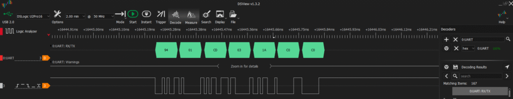
Communication in the reverse direction (acknowledgment) produced this pattern:
94 01 cd 03 18 c0 c0
94 01 cd 03 19 c0 c0
94 01 cd 03 1A c0 c0
| Byte | Meaning |
|---|---|
| 94 | Header → fix array size 4 |
| 01 | Response type |
| CD 03 18 | Message ID |
| C0 | nil error |
| C0 | nil result |
This translates to [1, msgid, null, null]:
Conclusions
This RPC-based system provides a flexible and reliable way to communicate between an MPU and MCU, allowing both synchronous calls and asynchronous notifications. Capturing and analyzing the data with a logic analyzer confirms the integrity and behavior of the protocol.
I hope you enjoyed this analysis and gained a clear understanding of how this RPC implementation works at the lowest level. Often, we use libraries without thinking about what happens “under the hood,” but peeling back the layers with a logic analyzer reveals the true elegance and efficiency of the MessagePack protocol over UART.
If you found this breakdown useful or have any questions about the byte-level decoding, please drop a comment below. I’d love to read your thoughts and hear about your own experiences debugging embedded communications!
Useful links: https://github.com/arduino/arduino-router
Pingback: Community spotlight: MyEmbeddedStuff | Arduino Blog
This was great – thank you! I had no idea the bridge library was using UART, and this is the first I have ever heard of the MessagePACK protocol, but it sounds straightforward enough. I love learning details like this – thanks again!
The Router Bridge is made up: UART2/ttyHS1 (at MPU side) and LPUARt1 (Serial2) at MCU side. Confirmed. If you want, I can send to you the test sketch at MCU side and cli commands at MPU side.
The Router Bridge is made up: UART2/ttyHS1 (at MPU side) and LPUARt1 (Serial2) at MCU side. Confirmed. If you want, I can send to you the test sketch at MCU side and cli commands at MPU side. ok
Hi Golam Mostafa. On the MPU side, it makes sense that it’s ttyHS1 based on what I mentioned in the post, but on the MCU side, I had Serial1 written down instead of Serial2. I might have mixed them up. Thanks for the contribution!